
The circuit presented here can be used in PCOs for displaying the actual bill. The comparative disadvantages of the presented circuit are as follows:
1. The calculator used along with this circuit is required to be switched ‘on’ manually before making a call.
2. Certain manual entries have to be made in the calculator; for example, for a pulse rate of Rs 1.26, number 1.26 is to be entered after switching ‘on’ the calculator followed by pressing of ‘+’ button twice. However, possibility exists for automating these two functions by using additional circuitry.
In telephony, on-hook condition is represented by existence of 48V to 52V across the line. Similarly, the off-hook condition is represented by the line voltage dropping to a level of 8V to 10V (depending upon the length of the local lead line (local loop) from telephone exchange to the subscriber’s premises as well as upon the impedance of telephone instrument). Handset is normally lifted either for dialing or in response to a ring.
In the circuit shown in Fig.1, when the handset is off-hook, the optocoupler MCT2E (IC1) conducts and forward biases transistor T1, which, in turn, forward biases transistor T2 and energises relay RL1. In energised condition of relay, the upper set of relay contacts connects the positive supply rail to PLL (phaselocked loop) IC2 (LM567) pin 4, while the lower set of relay contacts couples the positive telephone lead to input pin 3 of LM567 via capacitor C1 and resistor R3.


The negative telephone lead is permanently capacitively coupled to ground via capacitor C2. As soon as call matures, 16kHz tone pulses would be pumped into the telephone line by the telephone exchange at suitable intervals. This interval depends on the pulse rate of the place called and also the time of the day and whether it’s a working-day or holiday. On receipt of 16kHz pulse, output pin 8 of IC LM567 (which is tuned for centre frequency of 16 kHz) goes ‘low’ for the duration of the pulse. The output of IC2 is coupled via transistor T3 to optocoupler IC3. The output of this optocoupler is used to bridge the ‘=’ button on a calculator (such as Taksun make), which has the effect of pressing the ‘=’ button of the calculator.
Considering that pulse rate for a specific town/time/day happens to be Rs 1.26 per pulse, then before maturity of the call one enters 1.26 followed by pressing of ‘+’ key twice. Now, if a total of ten billing pulses have been received from exchange for the duration of the call, then on completion of the call, the calculator display would show 12.60. The telephone operator has to bill the customer Rs 14.60 (Rs 12.60 towards call charges plus Rs 2.00 towards service charges).
For tuning of the PLL circuit around IC2, lift the handset and inject 16kHz tone across the line input points. Tune IC2 to centre frequency of 16 kHz with the help of preset VR1. Proper tuning of the PLL will cause LED (D6) to glow even with a very low amplitude 16kHz tone.

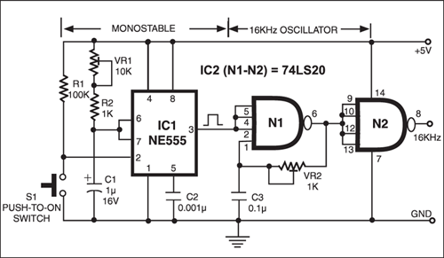
EFY Lab note. Arrangement used for simulating a 16kHz pulsed tone is shown in Fig. 2. Push-to-on switch is used for generation of fixed-duration pulse for modulating and switching on a 16kHz oscillator.
For more details regarding pulse rates, pulse codes, etc, readers are advised to go through the tariff rates and pulse code information given in the beginning pages of telephone directories, such as MTNL, Delhi directory, Vol.I.


Need a pco billing machine with monitor and without a printer
Need one mc with or without printer give me rate urgently
I need machine without printer pls urgent
what is the password for setting CALL RATES for CPD BRAND PCOM-1 machine. PLEASE HELP TO ANSWER MY QUESTION URGENTLY.
What is price of the pco billing machine all set
Fig.1 and Fig.2 are the same. Fig.1 description does not match with the Figure.
We have corrected Fig. 1.
Thanks