 Air pollution and concern about air quality is not something new. Complaints were recorded even in the 13th century when coal was first used for industrial purposes in London. From the middle of the 19th century, the atmosphere of major British cities was regularly polluted by coal smoke in winters, giving rise to the infamous mixture of fog and smoke known as smog. Today the emphasis has shifted from pollution problems caused by the industry to the ones associated with motor vehicle emissions.

Air Quality Index
Air Quality Index, or AQI, is a number used by government agencies to communicate to the public how polluted the air currently is, or how polluted it is likely to become. As AQI increases, an increasingly large percentage of the population experiences severe adverse health effects.
Different countries have their own air quality indices corresponding to different national air quality standards. Some of these are Air Quality Health Index (Canada), Air Pollution Index (Malaysia) and Pollutant Standards Index (Singapore).
The national AQI was launched in New Delhi on September 17, 2014, under Swachh Bharat Abhiyan. There are six AQI categories (Table I) of the same. The proposed AQI considers eight pollutants (PM10, PM2.5, NO2, SO2, CO, O3, NH3 and Pb) for which short-term (up to 24-hour averaging period) National Ambient Air Quality Standards are prescribed.
For details, you may refer this link: click here
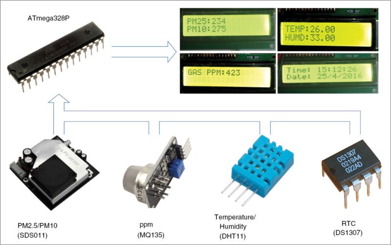
In this project the sensors used are SDS011, MQ-135, DHT11 and DS1307 (as shown in Fig. 1).
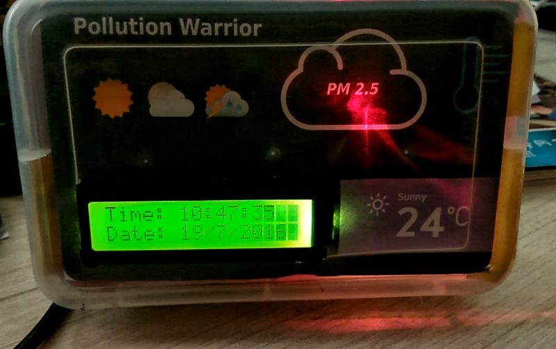
A typical PM2.5/10 air quality meter costs around US$ 200. Here we present an air quality meter for monitoring air particles, gas concentration, temperature, humidity and time, which costs around US$ 45 only. Block diagram of the air quality meter is shown in Fig. 1.


Circuit and working
Circuit diagram of the air quality meter is shown in Fig. 2. Heart of the circuit is ATmega328P (IC3). Other components used are voltage regulators 7805 (IC1 and IC2), 16×2 LCD display (LCD1), temperature and humidity module DHT11 (connected to CON4), gas sensor MQ135 (connected to CON3), PM2.5/PM10 sensor (connected to CON2) and a few others.

ATmega328P
It can be programmed with embedded software using a standard programmer or Arduino IDE. ATmega328P offers 23 input/output functional ports, and a 16MHz crystal oscillator is used to provide timing/clock reference.
Temperature and humidity module (DHT11)
This composite sensor contains a calibrated digital signal output of temperature and humidity. The sensor (connected to CON4) includes a resistive-type humidity measurement component and an NTC temperature-measurement device. Its output pin is connected to pin 12 of IC3.
Serial real-time clock (RTC) IC (DS1307)
It is a low-power, full binary-coded decimal (BCD) clock/calendar with 56 bytes of NV SRAM. Addresses and data are transferred serially through an I2C, bi-directional bus. The clock/calendar provides information about seconds, minutes, hours, days, dates, months and years. SCL and SDA pins of IC4 are connected toSCL (pin 28) and SDA (pin 27) pins of IC3, respectively.

Air quality sensor (MQ135)
The sensitive material of the sensor is tin-dioxide (SnO2), whose conductivity increases with concentration of gas. Change in conductivity is converted into output voltage signal, which varies corresponding to the concentration of the combustible gas. MQ135 is highly sensitive to ammonia, sulphide and benzene steam, smoke and other harmful gases. It is a low-cost sensor, suitable for different applications. Output of the gas sensor (CON3) is connected to analogue input pin 25 of IC3.
PM2.5/PM10 sensor (SDS011)
SDS011 is an air-quality sensor developed by Inovafit, a spin-off from University of Jinan (Shandong). Because of its size, it is probably one of the best sensors in terms of accuracy. While other sensors tend to focus on shrinking the sensor size, SDS011 has opted for a size tradeoff, allowing it to be used as a larger fan—larger the fan, better the quality.
SDS011 uses the principle of laser scattering in the air, which can be obtained from 0.3 microns to 10 microns suspended particulate matter concentration. Data is stable and reliable, and there is a built-in fan, digital output and a high degree of integration. UART port of SDS011 (CON2) is connected with IC3 UART port.
12V power/battery supply (CON1) is regulated to 5V using IC1 and IC2 and applied to the circuit. When the system is powered on, the device takes one minute to preheat the gas sensor before it is ready for operation. LCD1 displays proximate values of the four sensors connected to IC3. All these parameters are displayed on LCD1 at an interval of one second.
Software
The software is written in Arduino programming language. ATmega328P is programmed using Arduino IDE software. ATmega328P comes with a bootloader that allows to upload a new code to it without the use of an external hardware programmer. Select the correct board from ToolsBoard menu in Arduino IDE and burn the program (sketch) through the standard USB port in the computer.
Various operations are implemented in the code as follows:
RTC library is easy to use and can get the date, time and day of the week accurately.
DHT.temperature and DHT.humidity read temperature and humidity, respectively.
PM_CAL() function calibrates PM2.5/PM10 value.
The arrangement given below gives a rough approximation of the parts per million (ppm) levels of gas or pollutants. These values are calculated as:
[stextbox id=”grey”]count=analogRead(GasSensorPin);
Vout=(count*4.88)/1000.0;
Rs=((5.0*Rl)-(Rl*Vout))/Vout;
ratio=Rs/approx;
GasConc=146.15*(2.868-ratio)+10;
ppm=GasConc;[/stextbox]
Download source code: click here
Air Quality meter construction
A single side PCB for the air quality meter is shown in Fig. 3 and its component layout in Fig. 4. Suitable connectors are provided on the PCB for input and output.


Download PCB and Component layouts: click here
Assemble the circuit on the PCB to minimise errors. Carefully assemble the components and double-check for overlooked errors. Connect the power supply through 12V DC jack/battery and provide power supply to the circuit by connecting its Vcc and GND to CON1 on the PCB.
To test the circuit for proper functioning, check the power supply at TP1 and TP2 with respect to GND and ensure it is 5V.
All the mentioned parameters (PM2.5/PM10, temperature/humidity, ppm and time/date) are displayed on LCD1 at an interval of one second. In case the text is not visible on LCD1, adjust the potentiometer (VR1) connected with LCD1.
You may use cigarette smoke as polluted air for testing. PM value can reach up to 999 within five seconds when smoke is generated. The ppm value increases with smoke density, and temperature and humidity change as per the environment.
Biswajit Das was manager – R&D, EFY Labs till recently


Download link for code download dont work,
can fix this problem, please,
thanks
It has been updated now. You need DHTlib and RTClib libraries under Libraries folder.
What will be the cost of this project ………………at my residence here is a dumping yard they ruthlessly burning the dumps in open place pollution and smell is horrible so i want check the pollution level please help me out this………….
in place of sds110 can we use any other sensor
pls may i know the coding for this project
Dear Ramya, the codes are present on the second page of this article.
Sir any video reference for this project is available that makes easy for us to understand its working and about how to circuit is assembled.
sir how we upload sketches in atmega chip for pcb in this project ??
Sir i will make air pollution sensor
How to made plz guide me
sir,
we have to make a school project on Air Quality monitor, please guide for the same.
Hi sir i am a M.Tech student i am designing a low cost air purifier using MQ135 and air quality sensors in hospitals, small-scale offices and prevent large airborne particles such as air dust and hair, and other fine particles based prevent on micron size, first my requirement is to know the quality of air and based on feed-back for automatic air purifying can i use this sensor for my project ??
I interfaced aurdino with mq135 sensor, I got the output displaying in serial monitor.I Want to push these values to p10 led board using Arduino throw hub12 port How is it possible…?