
Bell. This part of the program is used for displaying the bell operating timings stored in the RAM. The operating timings are displayed one by one with a delay of 5 seconds between tow consecutive timings.
Set. The real time and bell timings are stored using this part of the software. Data is entered digitwise; for example, 08:30 a.m. will be stored a 0, followed by 8, followed by 3, and finally 0. Data is stored in 24-hour format.
Data fed from the keyboard is converted into equivalent hex and stored in RAM. Any particular operating timing can be deleted from the memory using ‘Delete’ key, provided the timing is already stored in the memory.
Run. Here the real time is compared with bell operating time. If the two match, the relay is operated.
DataCon. This part of the software is used for finding out the decimal equivalent of hex data. The microcontroller manipulates the hex data and converts it into BCD format for display.

Timer. The timer of the microcontroller is initialized to give an interrupt after every 10 ms. A real-time clock is generated using the interrupt. Also the display is refreshed during the interrupt service routine.
For real-time systems battery backup is very essential, because power failure affects the time keeping. In interrupt service routine, the availability of power supply is checked. If the power is available, displays are refreshed and the timer operates normally. However, during the power-failure period, displays are off and system is taken to ‘low power’ mode. In this mode only the timer part of the microcontroller remains activated while operations of all other peripherals are suspended. This considerably reduces the power consumption. When the supply gets restored, the controller starts operating in normal fashion.
Operating procedure
When the power is switched on, the display shows 12.00. Two settings are required in the timer: (a) setting of real time and (b) setting of bell operating timings. For setting real-time clock ‘Time’ key is used.

Storing of real time. To store real time, say, 05:35 p.m., flip ‘Run’/’Set’ key (S6) to set mode. The
display will show ‘0.000’. Press ‘Time’ key. Further pressing of ‘Time’ key will increment the data, like 0.000, 1.000, 2.000, and thereafter it will repeat 0.000, etc. To select the digit, press ‘Digit Advance’. This stores the present digit and the next digit is selected as indicated by the decimal pointer. Data is stored in 24-hour format. The time to be stored is 17.35, of which the first digit will be 1.000. The second, third, and fourth digits can be stored in similar fashion. After the fourthdigit, press ‘Digit Advance’ key once more. The display will show 1735 (with no decimal). Now press ‘Store’ to store the data.
 Storing of bell timings. The procedure to store bell operating timings is similar to that of setting real time. The only difference is that here data is changed by ‘Bell’ key in place of ‘Time’ key. Any number of bell timings (<20) can be stored in the same fashion. If the number of bell operating timings exceeds 20, the timer will not accept any new bell timings until one of the previously stored timings is deleted.
Deletion of bell operating timings. For deleting a particular timing, first store this timing using the steps given above. Then press ‘Delete’ key to delete the specific data from the memory.
Display of real time. If ‘Run’/ ’Set’ key is taken to run mode, real time will be displayed.
Checking of bell operating times. For checking the bell operating times, press bell key in ‘Run’ mode only. The stored bell operating timings will be displayed one by one with a delay of 5 seconds between two consecutive timings.
Programming
There are two ways to program the EPROM/ OTPROM (one-time programmable ROM):
1. Manipulate the control bits in the EPROM programming register to program the EPROM/ OTPROM
on a byte-by-byte basis.
2. Program the EPROM/ OTPROM with Motorola’s MC68HC705J in-circuit simulator.
The author has used the second method for programming the OTPROM.
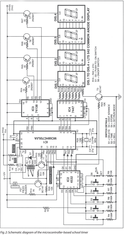
The source code and other relevant files, an actual-size, single-sided PCB for the circuits in Fig. 2 and Fig. 3, and its component layout can be downloaded below:
Download PCB and component layout PDFs: click here
Download source code: click here

sir please give source code