
Closed-circuit television (CCTV) uses video cameras to transmit signals to specific monitors. It differs from broadcast television in that the signal is not openly transmitted, though it may employ point-to-point wireless links. CCTV is often used for surveillance in areas that need security,such as banks, casinos, shops, departmental stores and airports or military installations.
Here is a remote-controlled CCTV switcher circuit to monitor six cameras on a single or dual monitor/TV. Then salient features of this switcher are:
1. Cameras: Six cameras with one way audio (audio incoming only)
2. Operation: Fully remote-controlled (infrared commander)
3. Front display: LCD to display the camera selected and all other functions parameters

4. Camera selection: Manual (you can select any camera of your choice by pressing number keys or camera up/down keys on the remote) and auto (the switcher selects the cameras one by one and holds videos of each camera till the preprogrammed time)
5. Auto mode: You can change ‘on’ time of each camera (hold time) individually through the remote. Time can be programmed from 0 to 255 seconds.
6. Camera bypass: You can set any camera in bypass mode by entering 0-second ‘on’ time for cameras which you want to bypass or don’t want to watch during auto mode.

7. Audio: One-way audio. In this model, you can hear the audio from the camera selected by the switcher.
8. Video: Two video-out RCA sockets with 75-ohm impedance 1Vp-p are available at the rear panel of the master unit. You can connect two monitors in these sockets.
9. Other features: Wide input voltage range, long-range infrared remote commander, microcontroller-based design supported with CMOS digital integrated circuits, liquid-crystal display to monitor the status and bilateral digital MOS switches for switching the analogue video/audio signals from cameras.
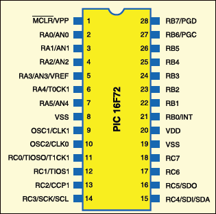
At the heart of the circuit is Microchip’s PIC16F72 microcontroller, which controls all the functions described in the design. Its pin configuration is shown in Fig.1.
The circuit
Fig.2 shows the main control circuit of the camera switcher. In this circuit, PIC16F72 microcontroller controls all the functions such as interfacing/initialising the LCD to display all the desired characters on the screen, decoding the RC-5 command on pressing the required keys of the remote control and providing high logic to enable corresponding bilateral CMOS analogue switches to connect the video signal from cameras to the video-output socket and audio signals to the power amplifier of the corresponding camera selected from the remote. Here we have used the remote control of an LG TV (remote code No. 6710V00079B). It is readily available in the market.
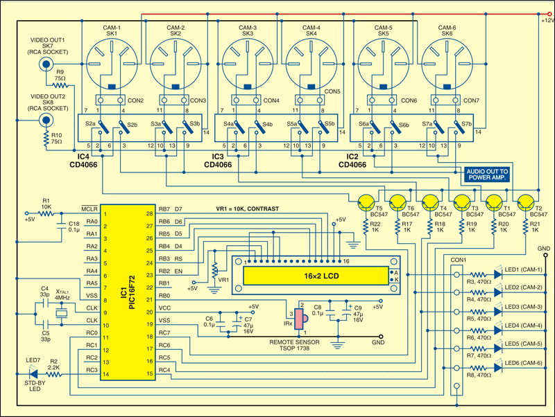
A remote sensor is connected to port RB0 (pin 21), called interrupt port, of the controller and the software initialises interrupt routines along with timer-0 interrupt to decode the RC-5 command.
Any transmission from the remote consists of two start bits, one toggle bit, 5-bit address and 6-bit command. Here we have not used the 5-bit address. A biphase-modulated bit can be thought of as two separate bits that are always the inverse of each other. A logical zero is represented by a ‘10’ pattern on the IR input, while a logical one is represented by a ‘01’ pattern. That is basically used to decode the received message.
Toggle bit is a particular property of the RC-5 protocol. This bit changes polarity every time you press a key and will remain unchanged as long as you hold the key. That enables the receiver to detect released keys, which helps to eliminate key bounces. We have also used this bit to detect so that if any key is kept pressed for a long time, the routine detects the command once, keeps the value in a general-purpose register called ‘passdummy’ (refer to ‘.asm’ file), and does not process and store any further command till the remote key is released. The stored RC-5 command value in register ‘passdummy’ is used to perform the necessary function given in the source code.
The LCD shows the camera number selected from the remote and mode of operation (auto/manual).
For camera-hold time set for auto mode and other display text information, please see the LCD screenshot in Fig.3. Use of the LCD makes the project more user-friendly.
All the cameras are to be connected to SK1 through SK6 (5-pin DIN connector) as shown in the circuit diagram.The extreme right and left pins are for 12V positive and negative supply (to be fed from the regulated power supply of the main switcher) for the built-in camera module. The 12 V power supply is permanently connected to all the cameras. Audio and video signals from the cameras are selected using switch pairs S2a-S2b through S7a-S7b (built inside IC2 through IC4) and fed to the audio power amplifier and video output sockets, respectively.


the source code link is curropted . plese correct it
The article is updated, you can download the source code.
thanks a lot
You are most welcome.
Hi.
Unfortunately it doesn’t work.
The hex file would be good for me.
Thanks
Hi Werner, Kindly elaborate your query.