

 While repairing or installing electrical machines in a building, the AC mains power supply is switched off from the mains electrical switchboard installed outside the building. There is a chance that someone who is not aware of the same may switch on the mains from outside. This poses a great danger for the technician working inside. Hence, an indicator like the one described here, which can be plugged into a nearby mains wall socket, might prove very useful for the technician.
This circuit can also be useful for people who are living in a place where there is frequent mains power cut.
Circuit and working
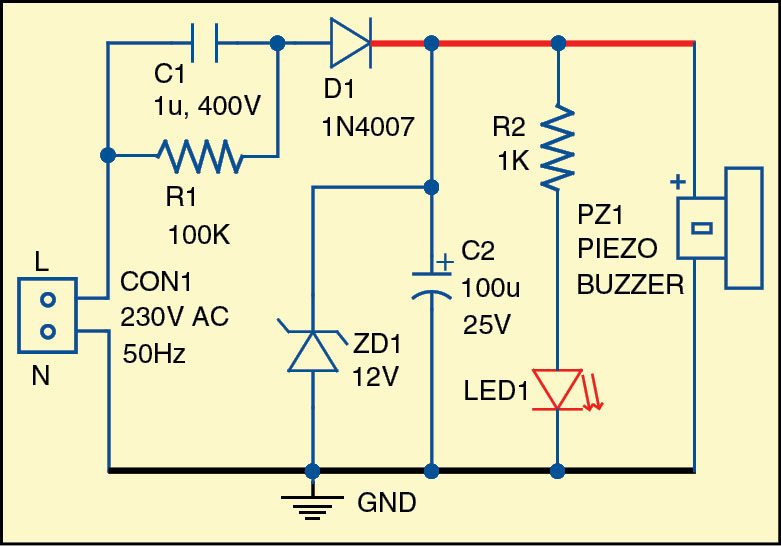
The circuit diagram of the light and sound indicator for the mains power supply is shown Fig. 1. The circuit is built around capacitors C1 and C2, resistors R1 and R2, diode D1, zener diode ZD1, LED1 and a piezo buzzer (PZ1). Resistor R1 and capacitor C1 are used for reducing the voltage and limiting the current. Diode D1 is a rectifier.
C2 is used as a filtering capacitor. Zener diode ZD1 limits the output voltage to around 12V. The value of zener diode should be equal to or lower than the maximum voltage of the buzzer and higher than the minimum voltage. Preferably, the buzzer should have a built-in oscillator working in the range of 6V-12V and requiring a current below 10mA. The frequency of the alarm sound is usually in several kilohertz (kHz).
LED1 is on when the mains power supply is present, and at the same time the buzzer produces sound. Resistor R1, capacitor C1 and diode D1 are selected depending on the current requirement of the buzzer.


Download PCB and component layout PDFs: click here
Construction and testing
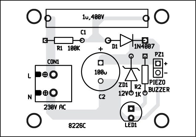
A single-side PCB of the simple light and sound indicator is shown in Fig. 2 and its component layout in Fig. 3. Enclose the PCB in a suitable small box in such a way that you can use it during repair work or installation. Ensure proper wiring to avoid any mistake.
Petre Tzv Petrov was a researcher and assistant professor in Technical University of Sofia, Bulgaria, and expert-lecturer in OFPPT, Casablanca, Kingdom of Morocco. He is currently working as an electronics engineer in the private sector in Bulgaria


Does the buzzer stop after a few seconds or it will keep buzzing until the circuit is disconnected from main power, and if not how to make it stop buzzing after a few seconds so I do not need to disconnect it every time, Thanks.
Here, the buzzer will continue to sound until it is disconnected from AC mains. Stop buzzing after a few seconds is not the main goal of this circuit. If you required such a circuit then the application/usage is different. That will be like an AC mains power resumption alarm given on the link here:
https://www.electronicsforu.com/electronics-projects/power-resumption-alarm-and-low-voltage-protector
https://www.electronicsforu.com/electronics-projects/automatic-power-resumption-alarm