Generally, line follower robot is microcontroller-based. Here we describe a line follower robot without microcontroller for those who are not familiar with microcontrollers. It is a simple project, which can be taken up as a classroom assignment. It lays the foundation for building your own behaviour-based (simulated) robot. The robot uses interfaces for the sensors to make the behaviour of the robot as versatile as possible. Two light detectors are mounted at the front of the robot. Also, a path is provided for the robot to follow—either a black track (using black colour tape) on a white floor or a white track on a black floor.
Circuit description
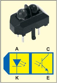
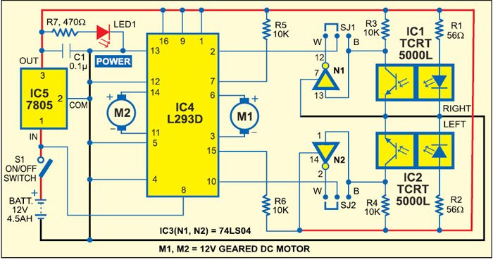
Fig. 1 shows the circuit of the line follower robot. It comprises two TCRT5000L reflective optical sensors (IC1 and IC2), inverter 74LS04 (IC3), motor driver L293D (IC4), regulator 7805 (IC5) and a few discrete components.
TCRT5000L optical sensors are used as line follower robot sensors. The TCRT5000L reflective sensor includes an infrared emitter and photo-transistor in a leaded package. The sensor and its internal details are shown in Fig. 2.
When an object comes in the sensing area, the emitted IR light reflects off the object back to the photo-transistor. So the amount of light energy reaching the detector increases. This change in light energy or photo-current is used as the input signal to activate the motors of the line follower robot.
The collector current of the photo-transistor is also dependent on the distance of the object’s reflector surface from the sensor. The intensity of the reflected signal returning to the detector depends on the surface over which the robot moves. White surface reflects maximum infrared signal, while black surface absorbs maximum infrared signal.
Motor driver L293D is interfaced with sensors and controls the 12V geared DC motors M1 and M2. The L293D is a quadruple high-current, half-H driver. It is designed to provide bidirectional drive current of up to 600 mA at 4.5V to 36V. The device is designed to drive inductive loads such as motors as well as other high-current/high-voltage loads in positive-supply applications.
The motor drivers are enabled in pairs. When enable input pins 1 and 9 of IC4 are high, the associated drivers for M1 and M2 are enabled and their outputs pin 3 and 6, and pins 11 and 14, respectively, are active and in phase with the inputs.
With the proper data inputs, each pair of drivers forms an H-bridge reversible drive suitable for motor applications. Motors M1 and M2 rotate in forward direction (say clockwise) when both the sensor outputs are low.
If you want the robot to follow a black track (made using black-colour tape) on a white floor, you need to connect jumpers SJ1 and SJ2 to B terminals as shown in Fig. 1. The robot will move as follows: When the left sensor, say IC2, detects the black track, the robot turns left. When the right sensor, say, IC1, detects the black track, the robot turns right. When both the sensors are in white surface then, the robot moves in forward direction.
If you want the robot to follow a white track change the jumpers’ positions towards W terminals. As the reflector sensor moves on the black surface, the emitted signals are absorbed by the black surface and both the inverters (N1 and N2) invert to low. These low signals are fed to the motor driver L293D and the robot moves forward. When the left sensor, say IC2, detects the white track, the robot turns left. When right sensor, say IC1, detects the white track, the robot turns right. When both the sensors are in black surface then the robot moves in forward direction.
The circuit is powered by a 12V DC battery. IC 7805 is used to provide regulated 5V supply to the circuit. Capacitor C1 bypasses the ripples from the regulated supply. LED1 acts as the power-‘on’ indicator and resistor R7 limits the current through LED1.
Construction and testing
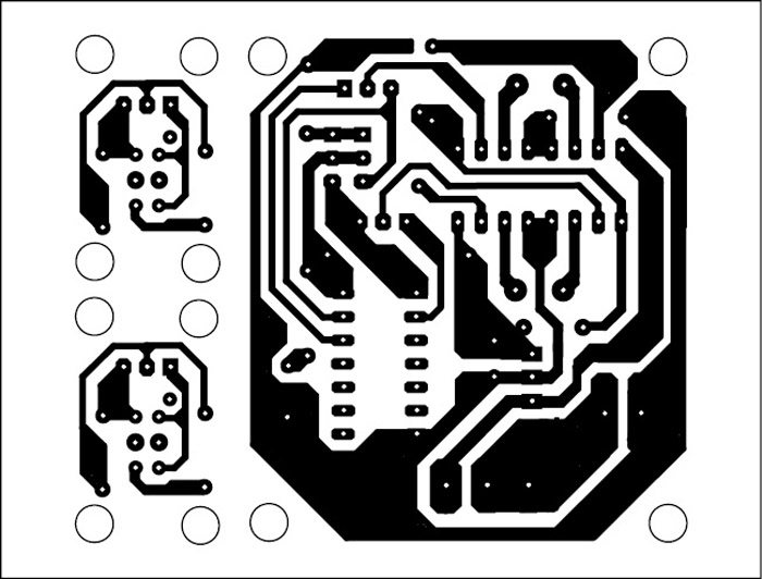
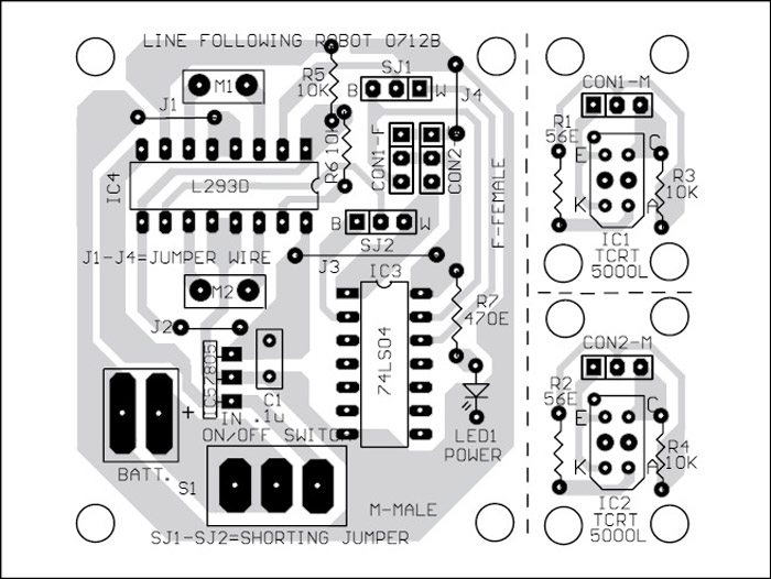
A single-side PCB for the line follower robot is shown in Fig. 3 and its component layout in Fig. 4.
The sensors sections should be separated from the main PCB by cutting along the dotted lines. Right and left sensors should be mounted on the front of the robot with both the sensors facing towards the ground. Distance between the right and left sensors should be aligned properly as per the width of the track on the ground.
Download PCB and Component Layout PDFs: click here
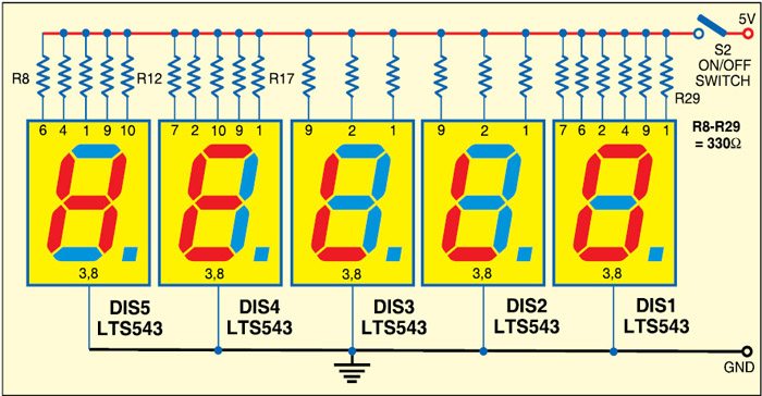
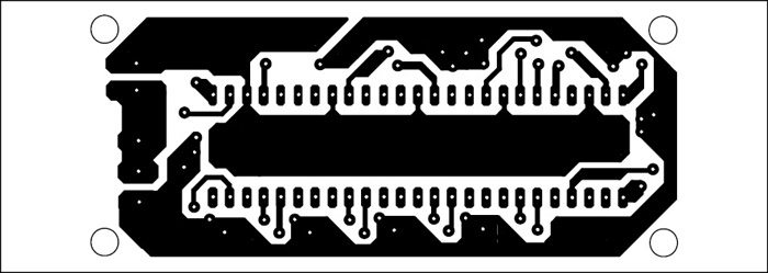
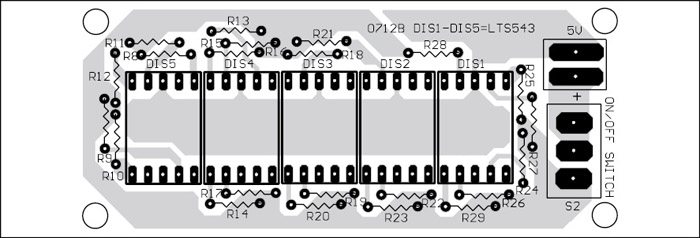
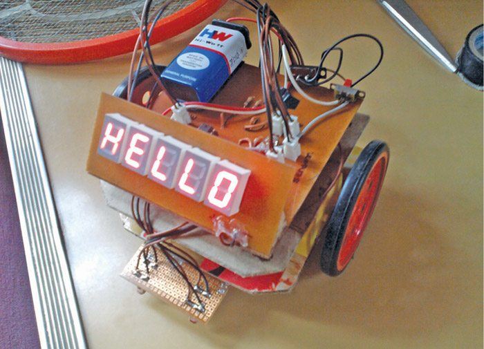
Assemble the circuit on a PCB as it minimises time and assembly errors. Carefully assemble the components and double-check for any overlooked error. Use of IC bases for IC3 and IC4 is recommended. Before putting the ICs, always check the correct supply voltage. Suitable connectors are provided on the PCB to connect geared motors M1 and M2 and sensors IC1 and IC2. Connect the motors and power the circuit with a 12V battery. Place the robot on the track. Sensors sense the white or black track on the surface and the robot follows that track. A ‘hello’ message can be displayed on top of the robot by using the circuit shown in Fig. 5. An actual-size, single-side PCB for Fig. 5 is shown in Fig. 6 and its component layout in Fig. 7. Working prototype photograph is given in Fig. 8.
The author is a BE final-year student of information technology. His interests include electronics and robotics, website designing, software development and microcontrollers


What are the values of resistors used in the Hello msg and can you post its lower view too
if it is possible that after connection and without any programming it will show HELLO
The whole robot is non programmed. HELLO also configured just by making required segments HIGH and rest are left as LOW.
Yes, the circuit Fig.5 is configured to display HELLO. It does not require programming.
I think these resistors are current limiters, so best value could be 330 to 660 ohms
Best one will be 470 Ohms
Please teel me that what willl happen if we are using black line follower and both the sensors sense black colour. will it move forward?
Thank you
Both on black means no movement.
Hello sir I am facing problem . Only one motor is working another motor is stop when the jumper position is on white and same as another sir please suggest me what I have to do
I need the components list in English and cost estimation.please
Please send me the component list….. I need it urgently
Hello please help me , one of my motor doesnt work while other one is working just fine i cant seems to find the error and im stuck here. Can you tell me what i did wrong.
Hello sir. I have a problem where one of my motors work and other one doesnt work .Please help me to fix this problem.
Hi,
If I wanted to add in a circuit breaker design that was to stop power going to the motors once an object has been detected how would I go about doing this.
Many thanks
Circuit diagram & explanation of the line follower robot by using IC L293D