
 Electromyography (EMG) is a technique of recording muscular activities by measuring the potential difference across a muscle of interest. EMG signal acquisition is the latest trend as it paves way for a new method of human-machine interface (HMI). Here, the signals sent by brain are received as a potential difference across the muscle. The signals are very weak in strength and are inherently embedded in noise and a large offset of the electrodes; therefore special procedures are often required to extract EMG signals of good quality.
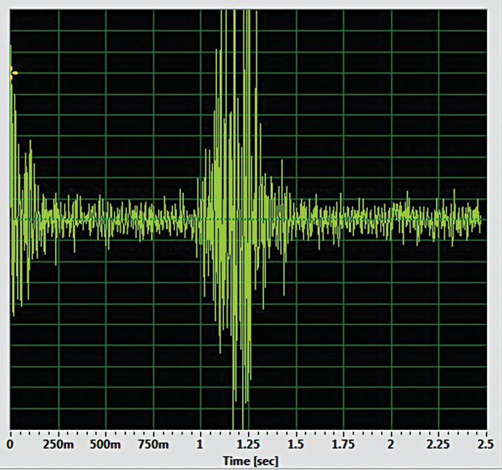
The circuit described here helps in making the analogue front end (AFE) of a simple and cost-effective EMG acquisition system. The circuit is specially designed for battery-operated portable systems. You can see the acquired EMG signals on a PC-based oscilloscope or a normal oscilloscope for simplicity. One such PC-based oscilloscope (freeware) can be downloaded from http://www.zeitnitz.eu/scope/scope_141.exe
Circuit and working
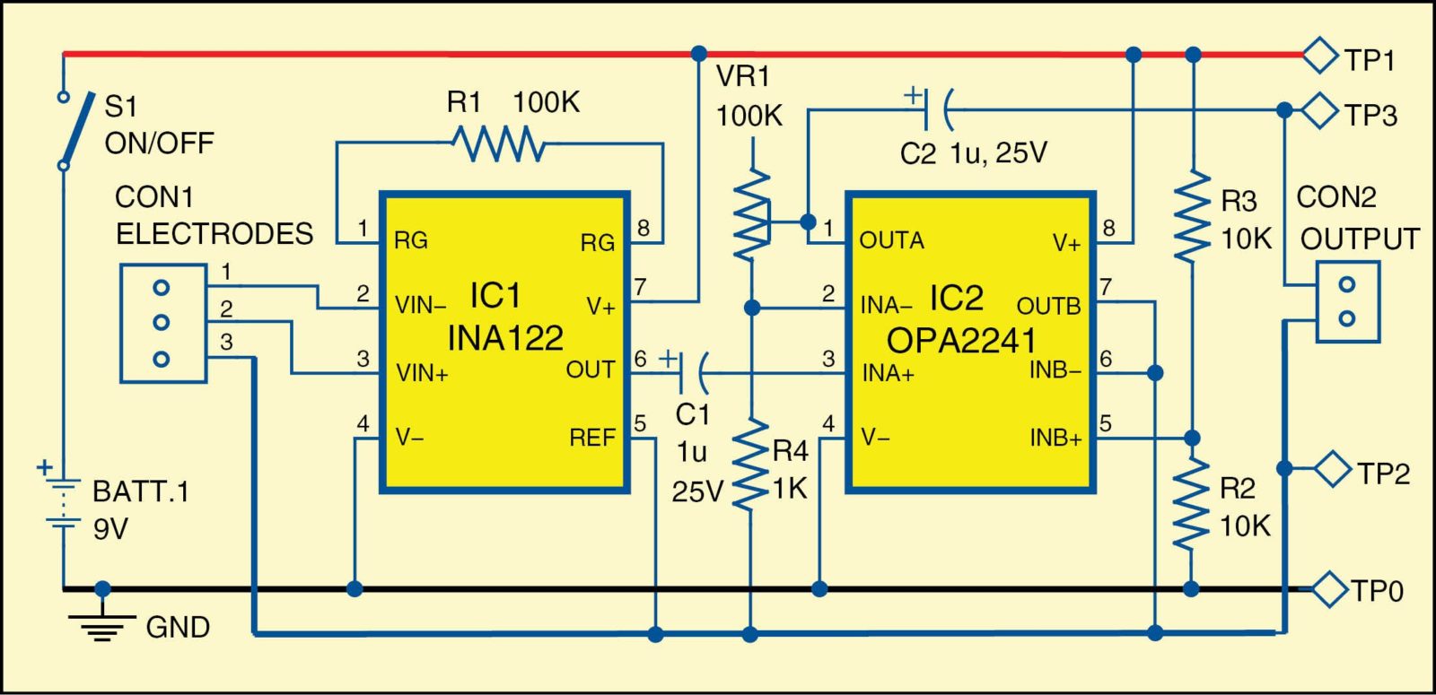
The circuit diagram of HMI through EMG is shown in Fig. 3. Starting from the left, two electrodes attached to a muscle are connected to a single-supply instrumentation amplifier INA122 (IC1), which amplifies the voltage difference between the two electrodes, rejecting any signal that is common to both—thereby removing much of the noise and 50Hz AC EMI. Resistor R1 determines the gain of the output of IC1.
It is difficult to deal with the bi-polar nature of the bio-signals. To overcome this problem, we use virtual-ground topology or split-rail topology, which splits the main power rail into two rails—one having Vcc and the other with half of Vcc (virtual ground). The created virtual ground acts as the pseudo-zero voltage and thus makes the output to swing between 0 and Vcc with virtual ground as zero volts, which makes the entire portion of the EMG wave available and also in the positive range only, thus making this topology ideal for interfacing with digital systems or microcontrollers.

IC1 is specifically designed for single-supply operations, for which it includes voltage translators and overvoltage protection. The electrodes are directly attached to the muscle. Prior to attaching the electrodes, clean the patient’s skin with alcohol for removing dirt and apply an ultrasound gel. Two electrodes are attached over the muscle of interest and the third one (reference) is connected to an area preferably in the joints where there are less muscles. The reference electrode should only be connected at pin 3 of CON1. It is vital as it provides the common-mode signal.
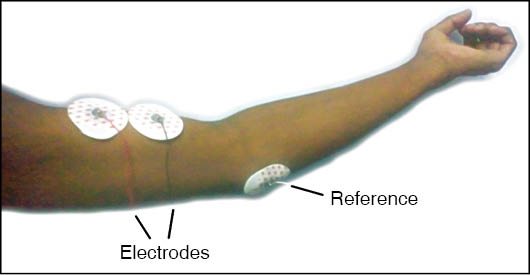
The reference is connected to the virtual ground and pin 5 (Vref) of IC1, so care must be taken to isolate the patient from ground. The patient must not touch any grounded metal, which can cause drainage of common-mode voltage and thus raise the amplitude of the output and inject a lot of noise.
The output from instrumentation amplifier IC1 is fed to a non-inverting amplifier built around OPA2241 (IC2) via capacitor C1, which removes the DC offset from the electrodes. The amplified output signal from IC2 is sent to the PC oscilloscope via an audio jack to get the display of the waveform.

Download PCB and component layout PDFs: click here
Construction and testing
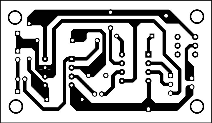
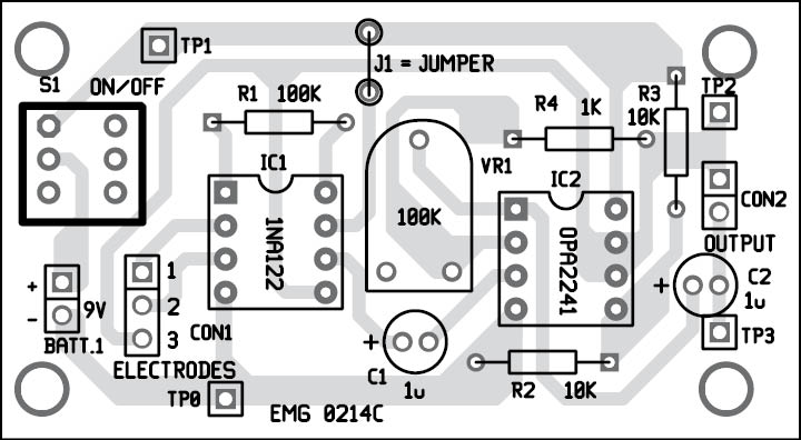
 A single-side PCB for the HMI circuit is shown in Fig. 4 and its component layout in Fig. 5. After assembling the circuit on PCB, enclose it in a suitable plastic case.
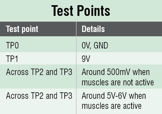
Fix a three-pin connector for the electrodes and two-pin connector for output. Also fix a two-pin connector for power supply on the front side of the panel. Please note that electrode connected to pin 3 of CON1 is the reference electrode and it should be in contact with a joint where there are less muscles. We used ECG electrodes during testing as they are easily available in medical stores. For troubleshooting, verify the voltages at different test points shown in the table.
Venu S. Dharan is a third-year B.Tech student in engineering physics whilst Siva Sankar A., Suparna S. Nair and Surajnath P. are third-year B.Tech students in electronics and communications from National Institute of Technology, Calicut. Currently, they are doing research on human-machine interface technology.


Hence I Wonder and voted for Amazing idea!!!!!
Queries:
1) Can i use any other Standard Instrumentation Amplifier Since this one cost too much in my area which can give the same accuracy???
2) Can I have take a look at the readings of Your Experiment to compare with my Reading for hand muscles..
3) please give me recommendation for The EMG cables to take accurate i’ve use ECG as you mentioned get too much noise…
Sir, Can I please receive the Working or Operating Video of this Project…
Thank YOu for Your warm responce….