


This IR motion sensor relay switch circuit is designed for use with all kinds of medium-power automobile/domestic 12V DC loads. It is a simple solid-state relay (SSR) switch, controlled by a standard passive infrared (PIR) motion sensor module. A PIR sensor is an electronic device that can measure IR light radiating from objects in its field-of-view.
Apparent motion is detected when an IR source with one temperature (such as a human being) passes in front of an IR source with another temperature (such as a wall). The PIR sensor module, centred on a PIR sensor, has elements made of crystalline material that generates an electric charge when exposed to IR radiation.
IR motion sensor relay switch circuit
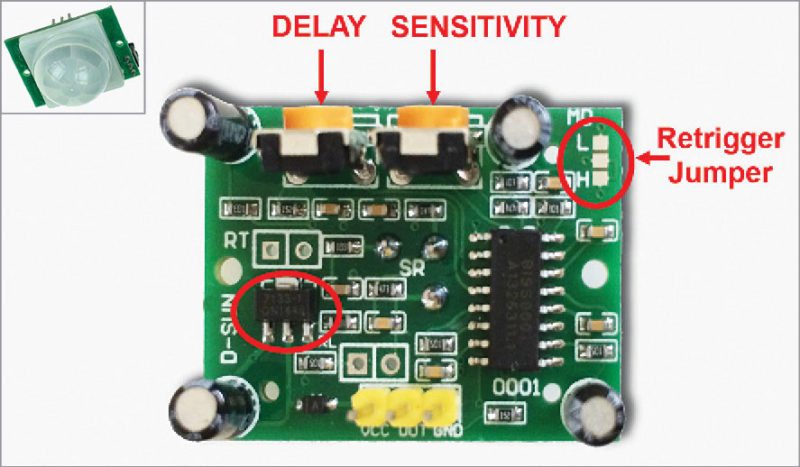
Changes in the amount of IR striking the element change the voltages generated, which are measured by an onboard circuitry. The module contains a special filter called Fresnel lens, which focuses IR signals onto the sensor element. As ambient IR signals change rapidly, onboard circuitry triggers the output to indicate motion. Fig. 1 shows the PIR motion sensor module. It is usually hidden behind a translucent dome shaped cover as shown in the inset in Fig. 1.

Circuit operation
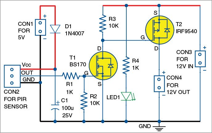
Circuit diagram of the IR motion sensor relay switch is shown in Fig. 2. It is built around a PIR motion sensor module (connected across CON2), MOSFETs BS170 (T1) and IRF9540 (T2), rectifier diode 1N4007 (D1) and a few other components.
The PIR sensor module has a 3-pin connection for Vcc, output and ground, and provides a single output that goes high when motion is detected. It also has a 2-pin jumper selection for single or continuous trigger output mode. The two positions are labelled H and L (Fig. 1).

When the jumper is at H position, output goes high whenever the sensor is triggered and retriggered. In position L, output goes high and low like a monostable timer every time the sensor is triggered. Retriggering pulse does not affect the output duration.
The circuit presented here is in repeatable trigger mode and turns T2 on when sensor output goes high. Output of the PIR sensor module is connected to the base of T1 (BS170) via resistor R1.
When motion is detected, PIR sensor output goes high to about 3.3V. The high-level, standard TTL output from the sensor-module switches on MOSFET T2 through T1, and T2 is closed by this action. As a result, the connected DC load is powered through T2 for a finite duration, determined by the time-delay setting of the PIR sensor module. Usually, the PIR sensor module includes an onboard time control preset pot (Fig. 1), which is adjustable from seconds to minutes. LED1 is the power-on indicator.

Download PCB and component layout PDFs: click here
Construction and testing
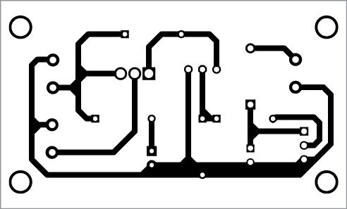
A single side PCB for the IR motion sensor relay switch is shown in Fig. 3 and its component layout in Fig. 4. Enclose the PCB in a small box so that you can connect 12V IN and 12V OUT easily at the rear side of the box. Install the PIR sensor at a suitable place and connect it to the PCB using a three-wire cable.
EFY notes
1. During initial power-up, the circuit automatically switches to active mode for a while and then shifts back to sleep mode.
2. p-channel power MOSFET IRF 9540 (in TO-220 package) is preferred universally for all commercial/industrial applications at power dissipation levels up to approximately 50 watts.
3. According to the data sheet, the PIR sensor requires an initial stabilisation time of 10 to 60 seconds in order to function properly. During this time, any motion in its field-of-view (approx. 6 metres) should be avoided.
The article was first published in June 2016 and has recently been updated.

Sir, Do you have the same similar with a BC547 ?
is there any code for this circuit
Hi Mishal, there is no source code for this circuit.