


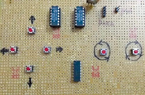
 Here is a simple joystick to control a robot to move in forward, backward, right, left, clockwise (CW) and counter-clockwise (CCW) directions using six buttons. It is cheaper than most other joysticks available in the market. The author’s prototype is shown in Fig. 1.
Circuit and working
Circuit diagram of the joystick for the robot is shown in Fig. 2.
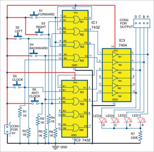
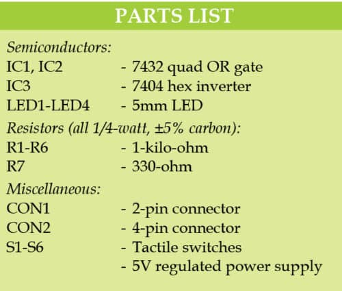
It is built around two quad OR gates 7432 (IC1 and IC2), hex inverter 7404 (IC3), four LEDs, six tactile switches (S1 through S6) and a few other components.

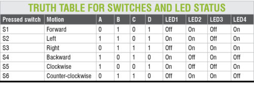
Logic for each move, like forward, backward, left, right, CW and CCW rotations, is based on the truth table using 6×4 encoder circuit formed by IC1, IC2 and IC3 logic gates. On pressing any one of the six switches (S1 through S6), a corresponding binary-coded decimal (BCD) code is generated as per the truth table.
When input to OR gate goes high, its output is high. The corresponding output is connected to input pin of NOT gate (hex inverter). When input to NOT gate is high, its output is low. Same is the case with other inputs.
All input lines of OR gates are pulled down to ground using resistors R1 through R6. When forward switch S1 is pressed, output of OR gate N1 of IC1 goes high, which makes N2 of IC1 (OR gate) go high. At the same time, it makes OR gate N3 of IC1 go high, which makes N1 of IC2 (OR gate) go high.
Outputs of IC1 and IC2 are fed to input pins 1 and 5 of IC3 (NOT gate), respectively. Before feeding the signals to IC3, code generated is 1010. But after passing through IC3, output becomes 0101. This is the required logic for moving the robot in forward direction as per the truth table.
Similarly, when backward switch S4 is pressed, it makes output gate N4 of IC1 and output gate N2 of IC2 go high. Before the signals reach IC3, code is 0101, and after passing through IC3, it becomes 1010. This is the required logic for moving the robot in backward direction as per the truth table.
Output codes generated for all input switches are available at connector CON2.
Construction and testing
An actual-size PCB layout of the joystick for the robot is shown in Fig. 3 and its components layout in Fig. 4.
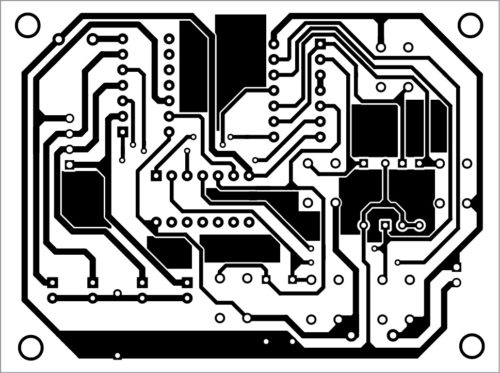
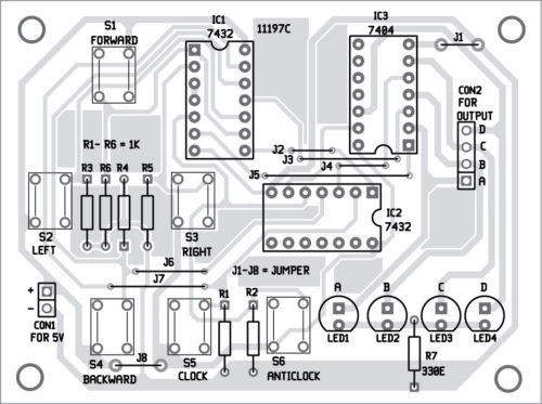
Download PCB and Component Layout PDFs: Click here
After assembling the circuit on the PCB, connect a 5V DC across CON1. Connect all LEDs (LED1 through LED4) to the front panel for indicating output. LEDs will glow according to the code generated, indicating high (logic 1) or low (logic 0) status. That is, status of each input switch can be checked through the glowing of the respective LED and the truth table.
You can feed the signals from CON2 either to input of the motor controller circuit to drive the robot or to input of the joystick to control the cursor in a video game application.
A readymade RF transmitter to control the robot is easily available online or in the local market. The circuit can be used with the RF transmitter circuit to control the robot as shown in Fig. 5.
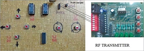
Connect 4-pin header (A, B, C, D) of the joystick with 4-pin input (D0, D1, D2, D3) of the RF transmitter. You will find a 6-pin header in the RF transmitter marked as D0, D1, D2, D3, +5V and GND. If you are using a separate supply for a joystick, do not forget to make ground common.
Sanjay Kumar Gupta is an electronics hobbyist
This article was first published on 22 February 2019 and was updated on 3 September 2019.
nice job
For the beginners in Robotics, this is the best training article. Start your work with the simple development like joystick robot and the other similar process and circuit. It will make you to understand the concept so that in the future you can develop your own complex and other useful circuit robots.
I tried it and it does not work
All outputs are high, and only goes into its correct mode when you press the switches.
Shouldn’t the outputs in CON2 be zero when powered on but they are all high?
Am I doing something wrong?
I used 74LS32 and 7404