
 At night, on highways, the high-intensity light from the headlight of heavy vehicles blinds oncoming light vehicle drivers (bike riders and car drivers) for a moment. This is the main reason for a large number of accidents on highways at night. By wearing this digital night vision goggle, drivers can drive their vehicle easily without any “Glare” problem.
Digital night vision goggle circuit
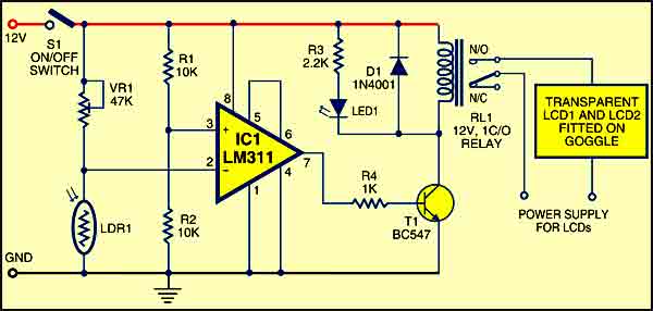
As shown in Fig. 1, at the heart of the circuit, is IC LM311 (IC1). IC LM311 is wired as a comparator. Its non-inverting pin 3 gets reference voltage (half of the supply voltage) through divider network formed by resistors R1 and R2. Inverting pin 2 gets the control voltage through the network of preset VR1 and light-dependent resistor LDR1.
At night, the resistance of LDR1 is very high and therefore the voltage at the inverting input of IC1 remains higher than at the non-inverting input and the relay remains de-energised to disable the transparent LCDs.
When light falls on LDR1, its resistance reduces. As a result, the voltage at the inverting input of IC1 goes below the voltage at the non-inverting input and the relay energises to enable the transparent LCDs (LCD1 and LCD2).
When the light from the headlight of the approaching heavy vehicle falls on the goggle’s LDR1, it senses light to energise the relay. This enables the transparent LCDs and their colour turns black. When the light goes away, the LCDs reset within a few seconds.

Construction & testing
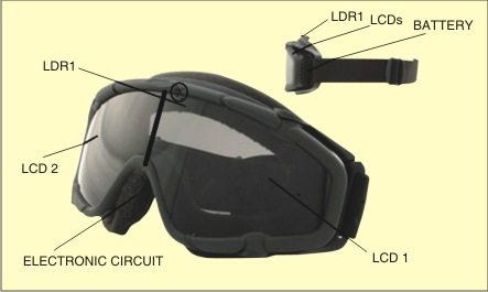
Assemble the circuit on a general-purpose PCB and enclose in a small cabinet. Fix the transparent LCDs on the helmet as shown in Fig. 2.
EFY note
- We have tested this circuit without the transparent LCDs.
- In case the transparent LCDs are not available, you can use this circuit as a light source by connecting two-three torchlights or bulbs in place of LCDs. The torchlights or bulbs may be fitted at the top of a helmet/car, with the proper orientation towards the ground.
The project was first published in January 2011 and has recently been updated.


explain the circuit diagram totally i’m not getting it.
I need Full description of this project including circuit diagram and program
Do you have any working video?
Please provide working video for it?
Where’s the proof that it works? All I see is theory. BTW, where can I buy the transparent LCD’s?
Transparent LCDs are available at electronic component shops or even try at mobile screen/parts shops