
 Useful for the elderly and ailing persons, this touch-sensitive panic button circuit sounds a panic alarm to catch the attention of others for immediate help. The touch plate fixed on the wall near the bedside gives an easy access to the person on bed rest so that he may call for assistance without much difficulty. Yellow LED3 on the panel indicates the call and the red LED indicates an immediate attention.
Panic button circuit
The circuit is based on the electric charge in the human body generated from within or obtained from the surrounding electric field. When the sensor plate is touched, the electric charge present in the body biases transistor T1 and it conducts. This triggers IC 7555 (IC1) and its output goes high for a while. IC 7555 is the CMOS version of the common timer IC 555.
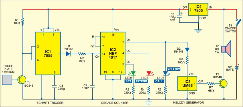
The high-going output pulse from IC1 triggers IC HEF4017 (IC2), which is a Johnson decade counter IC with ten decoded outputs. The counters within the IC advance one by one at the positive clock pulse on its clock pin 14, provided clock-inhibit pin 13 is low. Pin 15 resets the IC when it receives a positive signal.
Circuit operation
When IC2 receives the clock pulse from IC1 through diode D1 and resistor R2, its Q1 output goes high to power LED3 and melody generator IC3. The tone from IC3 is amplified by T2 and heard from the speaker. Forward-biased diode D2 and resistor R6 provide current to IC3.
When IC2 receives another clock pulse, its Q2 output goes high and the call tone stops and red LED lights to indicate the need for immediate attention. The green LED indicates the standby mode and glows at power-on. Capacitor C2 prevents accidental triggering of the alarm.

The Q3 output (pin 7) of IC2 is shorted with reset pin 15, so IC2 resets when it receives the third clock pulse.
In short, the first touch will make a call, the second touch will stop the call and light up the red LED, and the third touch will reset the IC and light up the green LED after getting the assistance. So if the red LED remains lit, it indicates that nobody has attended the person even after a call was made. IC4 and C3 provide regulated 5V DC to the circuit.

Construction & testing
The circuit can be easily assembled on a general-purpose PCB. Use 7555 and HEF4017 ICs for higher reliability, and 5mm glass LEDs for indication. The touch plate can be made from a 15×15cm aluminum or tin sheet. It should be connected to the circuit using a 1m plastic-jacketed wire. Fix the speaker at a place where the sound can be heard easily by the family members.
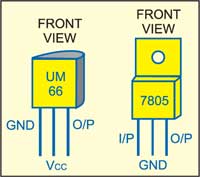
The circuit can be powered by a 9V PP3 battery or mains operated 9V adaptor. Fig. 2 shows pin configurations of UM66 and 6V regulators.
The article was first published in Februray 2006 and has recently been updated.


