 Here we show how you can control a wireless toy car through your PC’s serial port using a pair of ASK transmitter and receiver modules. The received signal is decoded by a P89V51RD2 microcontroller and fed to the motor driver circuitry to move the toy car in forward, backward, right or left direction. All the signals are in RF domain.
Controlling a wireless toy car
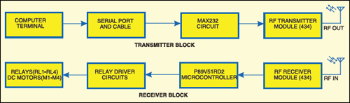
Above is the block diagram for PC based wireless toy car control. The different stages of wireless control are:
- Transmission of the control signals from a PC’s serial port
- RF transmitter and receiver
- Decoding of the received signals using the microcontroller
- Motor drivers
Asynchronous serial communication is established between the computer and P89V51RD2 microcontroller through wireless RF link. The microcontroller and computer are both synchronised with each other. The baud rate of data transfer is 1200.

Transmission of the control signal through PC’s serial port
The first part of the project is the transmission of control signals through the serial port of the PC. The control signals are W, S, D, A, Q, E, C, Z and U to control the toy car in forward, backward, right drift, left drift, sharp forward left turn, sharp forward right turn, sharp backward left turn, sharp backward right turn and stop, respectively. Each of the control signals is fed from the keyboard and sent through the serial com port. The signal is then transmitted wirelessly by the ASK transmitter module.
PC’s serial com port

There are many ports available at the base of your PC in order to send data to the connected peripherals. Serial port, parallel port and USB port are some of the ports for connecting to the peripherals.
The serial data port transmits or receives the data serially (1-bit data per TX or RX clock pulse). It is based on IEEE RS-232 standard, which defines voltages and baud rates for serial communication between devices connected to it. Most desktop computers have an RS-232 serial port as it has a very simple circuitry and is cheap and easy to handle.
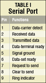
Windows-based 9-pin serial port DB9 connector has the configuration as shown here.
The RS-232 standard serial port has nine pins having different functions for transmitting and receiving data. Of these, only three pins (pins 2, 3 and 5) are mostly used for sending and receiving data. Only pins 3 and 5 are used in this project. The RS-232 standard has specific voltage levels for data logic 0 and logic 1 (-3 to -15V for logic 1, and +3 to +15V for logic 0). But the microcontroller defines logic 0 and logic 1 by voltage levels 0-0.5V and 4.5-5V, respectively. So you have to convert the RS-232 standard signal level into the microcontroller signal level. For that purpose, we have used a MAX232 converter.
For signal-level conversion, MAX232 requires four capacitors (10μF) and a 5V supply. Since we are using 9V supply, a single voltage source voltage regulator IC 7805 is required to supply power to MAX232. Now, the serial port signal, which is at RS-232 logic, can be converted into 5V TTL-level signal.
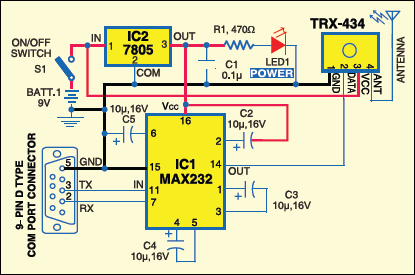
Transmitter circuit
The transmitter section built around MAX232 is shown above.
RF transmission
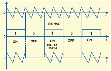
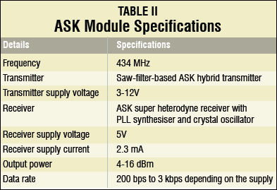
The 5V supply from 7805 voltage regulator IC powers the RF ASK transmitter module through its pin 3. This module actually collects the binary signal from the data pin (which is connected to the MAX232) and modulates this binary signal with amplitude-shift keying (ASK) digital modulation scheme by a carrier frequency of 434 MHz and transmits the data through the antenna. The concept of the ASK signal is shown here.
RF reception
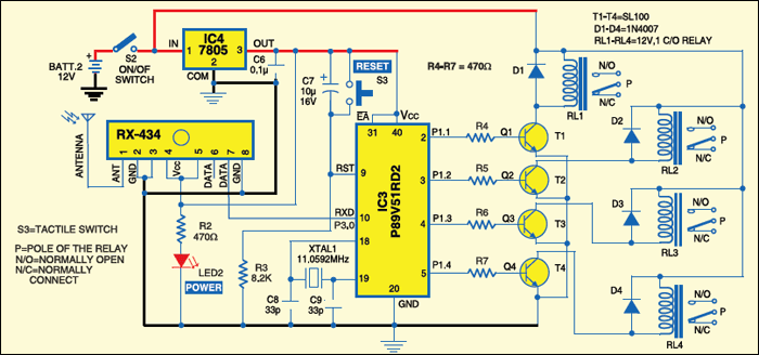
The ASK receiver module (Fig. 4) receives the 434MHz signal and demodulates it. The baseband signal is a 10-bit digital signal with the first bit as start bit, the following eight bits, as data bits and the last bits as stop bit. The received data is sent to the microcontroller. The RXD pin (p3.0) of P89V51RD2 microcontroller is connected to the data pin of the 434MHz ASK module receiver. So the P89V51RD2 detects the transmitted data at its pin 10 (RXD).
Decoding of the received signal with P89V51RD2
The P89V51RD2 is an 80C51 microcontroller with 64kB flash, 1024 bytes of data RAM, 32 input/ output (I/O) ports, three 16-bit timers/counters and two pins for serial data transmission and reception. Timer 1 is used for serial communication. It is operated with an 11.0592MHz crystal.
A key feature of the P89V51RD2 is its X2 mode option. You can choose to run the application with the conventional 80C51 clock rate (12 clocks per machine cycle) or select the X2 mode (six clocks per machine cycle) to achieve twice the throughput at the same clock frequency.
The Flash program memory supports both parallel programming and in serial in-system programming (ISP). It is also in-application programmable (IAP), allowing the Flash program memory to be reconfigured even when the application is running.
In this project, timer 1 (TH1) is used in mode 2 (8-bit auto-reload). It is used to set the baud rate. Here it is loaded with a value of E8 hex (or -24) and so the baud rate is set at 1200. The SCON register is loaded with a hex value of 50, indicating serial mode 1, where 8-bit data is framed with a start bit and a stop bit.
After timer TH1 is set, it starts running until the P89V51RD2 microcontroller is made off. The P89V51RD2 waits until it receives a start bit. After receiving the start bit, it receives the 8-bit data and places the data in SBUF register. Then the framing error is checked. If there is framing error, the byte received is discarded. Otherwise, the content of SBUF is compared with the ASCII code of alphabets W, S, D, A, Q, E, C, Z and U. When a match is found, the operation related to each alphabet is executed. Then the toy car stops or moves in a particular direction as per this value.
Driving the DC motors
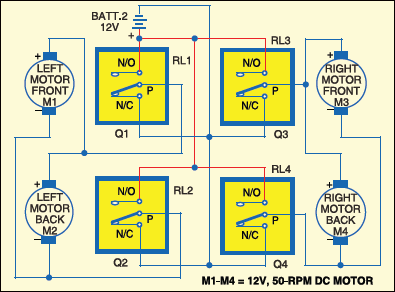
Port pins p1.1 through p1.4 of the microcontroller drive four relays through a relay-driver circuitry comprising transistors T1 through T4. The four relays, in turn, control four motors of the toy car (Fig.5). Two relays control the forward and reverse rotations of a motor. The left two motors are connected in parallel and so are the two motors of the right. So two motors are controlled simultaneously using two relays.
Each of the four relays is 12V, single- changeover electromagnetic type to control the PMDC motor (12V, 50-rpm). The relays play an important role in isolating the controlling circuit and PMDC motors to protect the microcontroller and other low-current devices from the relatively high-current-driven motors. Basically, these are switches that connect or disconnect the motors from the 12V supply. Control signals from the microcontroller energise or de-energise the relays. That is, when a control signal makes a pin of P89V51RD2 high, the transistor connected to it conducts to energise the corresponding relay.
Here +12V terminal of the battery is connected to normally-open (N/O) contacts of all the relays and the ground terminal is connected to normally-closed (N/C) contacts of the relays.
This means when all the relays are not energised, positive and negative terminal ends of all the motors connect to the ground terminal of the battery, so the motors will not rotate. If all the relays energise, ends of the motors connect to +12V and the motors don’t rotate. If any of the relays energises, one end of the respective motor connects to +12V and the other end to the ground. This makes the motor rotate. Energisation of the relay decides clockwise or anticlockwise movement of the motor.
Q1 output from the microcontroller is fed to the base of transistor T1. When Q1 is high, transistor T1 conducts and relay RL1 energises to make the pole (P) shift towards N/O contact. This connects +12V to the positive terminal of motor M1 on the front left of the toy car.
Relay connections
When Q2 output is high, transistor T2 conducts and relay RL2 energises to make P shift towards N/O contact.This connects +12V to the positive terminal of motor M2 on the left back of the car.
When Q3 output is high, transistor T3 conducts and relay RL3 energises to make P shift toward N/O contact. This connects +12V to the positive terminal of motor M3 on the right front. When Q4 output is high, transistor T4 conducts and relay RL4 energises to make P shift toward N/O contact. This connects +12V to the positive terminal of motor M4 on the right front.
When Q4 output is high, transistor T4 conducts and relay RL4 energises to make P shift toward N/O contact. This connects +12V to the positive terminal of motor M4 on the right back.
Controlling the toy car
‘W’ forward movement (Q1=1, Q2=0, Q3=1, Q4=0). The toy car moves forward when all the motors move clockwise. To achieve this, the output logic at Q1, Q2, Q3 and Q4 should be high (1), low (0), high (1) and low (0), respectively. Character ‘W’ is defined in the code to give 1010 bits in the output. That is, when you type ‘W’ character from the keyboard, the microcontroller generates 1010 bits at its port pins `p1.1 through p1.4. This signal is sent to relay-driver section T1 through T4.
‘S’ backward movement (Q1=0, Q2=1, Q3=0, Q4=1). The backward movement takes place when all the motors move anticlockwise. So signal 0101 is sent to relay-driver section T1 through T4. Character ‘s’ is defined in the code to give 0101 bits in the output.
‘D’ right drift (Q1=1, Q2=0, Q3=1, Q4=0 (for 54 ms) and Q1=1, Q2=0, Q3=0, Q4=0 (for 108 ms)). Right drift is possible by rotating the left motors at a high speed and the right motors at a low speed. This is possible with the pulse-width-modulated (PWM) pulse given to the right motors. The right motors are given a pulse train of 33 percent duty cycle so that these rotate at one-third the speed of the left motors. The car takes a right turn in forward direction resulting in a drift. So signal 1010 is sent for 54 ms and a signal of 1000 for the next 108 ms to transistors T1 through T4. Character ‘D’ is defined in the code to generate the 1010 and 1000 signals with 54 ms and 108 ms delays, respectively.
‘A’ left drift (Q1=1, Q2=0, Q3=1, Q4=0 (for 54 ms) and Q1=0, Q2=0, Q3=1, Q4=0 (for 108 ms)). Left drift is possible by rotating the right motors at a high speed and the left motors at a low speed. This is possible with the PWM pulse given to the left motors. The left motors are given a pulse train of 33 percent duty cycle so that these rotate at one-third the speed of the right motors. The car takes a left turn in forward direction, resulting in a drift. So signal 1010 is sent for 54 ms and signal 0010 for the next 108 ms to transistors T1 through T4. Character ‘A’ is defined in the code to generate 1010 and 0010 signals with 54ms and 108ms delays, respectively.
‘Q’ sharp-forward left turn (Q1=0, Q2=0, Q3=1, Q4=0). The toy car moves to the left sharply in the forward direction when the left motors are static and the right motors move clockwise. So signal 0010 is sent to transistors T1 through T4. Character ‘Q’ is defined in the code to generate 0010 bits in the output.
‘E’ sharp-forward right turn (Q1=1, Q2=0, Q3=0, Q4=0). The car moves to the right sharply in the forward direction when the left motors move clockwise and the right motors are static. So signal 1000 is sent to transistors T1 through T4. Character ‘E’ is defined in the code to generate 1000 bits in the output.
‘C sharp-backward left turn (Q1=0, Q2=0, Q3=0, Q4=1). Sharp left turn takes place when the left motors are static and the right motors move anticlockwise. The car moves to the left sharply in the backward direction. So signal 0001 is sent to transistors T1 through T4. Character ‘C’ is defined in the code to generate 0001 bits in the output.
‘Z’ sharp-backward right turn (Q1=0, Q2=1, Q3=0, Q4=0). The car moves to the right sharply in the backward direction when the left motors move anticlockwise and the right motors are static. So signal 0100 is sent to transistors T1 through T4. Character ‘z’ is defined in the code to generate 0100 bits in the output.
‘U’ stop (Q1=0, Q2=0, Q3=0,Q4=0). To stop the car, all the motors should be static. This is achieved by sending signal 0000 to the output of the microcontroller at its port pins p1.1 through p1.4. The character ‘u’ is defined in the code to generate 0000 bits in the output to stop the toy car.
Software program
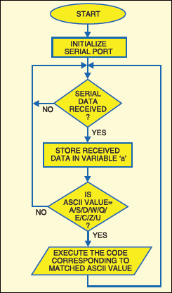
Here is the flow-chart of the program. The program is written in ‘C’ and compiled using Keil C software. The hex code generated using Keil software is burnt into the chip using Flash Magic programming software from NXP (Philips) Semiconductors.
Keil C μVision3 operations
- Run Keil μVision3 application from the desktop. From ‘Project’ menu, select ‘New Project’ option. Name the project as ‘efytoy.uv2’ and save it.
- Select microcontroller P89V51RD2 from the database under NXP (Philips) option.
- Right-click ‘Source Group1’ option in ‘Project Workspace’ window on the left-hand side of the screen. Click ‘Add Files to Source Group 1’ option to add the toycar.c file.
- Right-click ‘Target1’ option from ‘Project Workspace’ and select ‘Options for Target 1.’ The window appears as shown below.
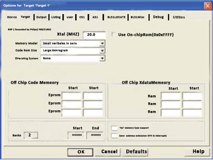
Options for Target 1 - Change the Xtal (MHz) value to 11.0592 as used in the project. Click ‘Output’ menu and tick the button against ‘Create HEX File’ option.
- Now close the window and go to the main window. Compile the project by clicking ‘Build Target’ option. The program will be compiled with the message as shown here.
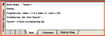
Now, the efytoy.hex code will be generated in the directory where the project file efytoy.uv2 is located. This hex code is used for programming the chip.
Programming the chip using Flash Magic
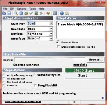
- Run the Flash Magic software and select the device as P89V51RD2 and ‘Erase all Flash’ option as shown above.
- In the ‘Advanced Option,’ uncheck ‘Use DTR to control RST’ and ‘Assert dtr and rst while com port open’ options.
- Browse the efytoy.hex file from your PC and load it onto the main screen. Press ‘Start’ button to program the chip.
Construction and testing
A single-side PCB of the transmitter circuit and its component layout, and a single-side PCB of the receiver circuit and its component layout is available for download here.
Burn the code into P89V51RD2 and mount the components on the receiver PCB.
Mount the populated PCB, 12V battery and four motors on a suitable chassis, preferably a 20×15 cm2 metal chassis. Use proper nuts and bolts to fix them firmly on the chassis. Four wheels, each of 7cm dia., are attached to shafts of respective motors.
After mounting the components on the transmitter PCB, connect the circuit to the serial port of the computer using a serial cable. If your PC has a USB port only, you may use a USB-to-serial converter. Now switch on the 9V power supply using switch S1.
Before sending the data from your computer, check which comport is connected to the circuit. Set the baud rate of the comport to 1200, stop bit to 1 and data bits to 8. Go to ‘Device Manager’ option from your desktop to do these settings. Now run a serial communication software such as Terminal v1.9b, select the com port and make the aforementioned settings. After completing all the settings and component assembly, switch on the power supply to the transmitter and receiver circuits.
Run Terminal v1.9b software and activate the connection by pressing ‘Connect’ button followed by W, S, D, A, Q, E, C, Z or U key on the keyboard. The ASCII code corresponding to that key will be transmitted serially in a 10-bit (1 start bit+8 data bits for ASCII code+1 stop bits) binary data stream. The toy car will move as per the input from the keyboard.
Source Code
The source code of this project is available here.
The project was first published in September 2010 and has recently been updated.