Prof Dr Dogan Ibrahim of the Near East University in Cyprus describes the basic principles of gas sensors and shows how a wireless gas sensor system can be designed
Gas detector systems are mainly used to sense the presence of gas leak in an area and then take some action, such as automatically shut down the source of the gas, or sound an alarm to inform the people in the area where the gas leak is occurring. Common gas detectors used at homes sense potentially hazardous gas leaks such as the carbon monoxide and then sound an alarm to alert the people at home that hazardous gas has been detected so that doors and windows can be opened, the source of the gas can be shut if possible, and people are alerted early enough so that they can leave the area.
There are many life threating toxic gases, the common ones being carbon monoxide, carbon dioxide, methane, sulphur and many others. Early gas detectors in the 19th century were not sensitive and were not electronic devices and they relied on everyday experiences and on the detection of some chemical reactions. For example, canaries were used to detect the presence of harmful gasses. Although the canary is a songful bird, it stops singing and dies quickly in the presence of such gasses, alarming the people around to leave the area. Similarly, chemical papers that change colour in the presence of harmful gasses were used to detect the presence of such gasses.
Nowadays there are many types of gas sensors available. Some sensors are sensitive to one particular gas, while some others are sensitive to a number of gasses. Modern gas sensors are designed using various technologies such as electrochemical, infrared, semiconductor, ultrasonic, holographic and others.
Some of the commonly used gas sensor chips are described briefly in the next section.
Semiconductor Gas Sensors
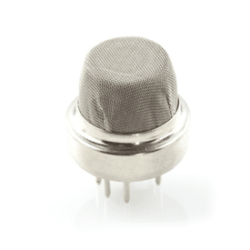
The MQ series of gas sensors are highly popular and are used in most domestic and industrial gas detection applications. These are semiconductor sensors with the SNO2 as the sensitive material. The sensor has low conductance in clean air, but its conductivity rises when subjected to the gas to be sensed. The change of the conductivity is converted to an analog output signal through a simple circuit. The detection ranges of these sensors depend upon the type of sensor used.

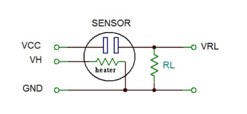
As shown below, MQ series of gas sensors require two voltage inputs: the heater voltage (VH), and the circuit voltage (Vcc). The heater voltage is specified as 5V and it can be AC or DC. The circuit voltage is 5V DC and should be connected as shown in the figure. In most application the same 5V voltage is used to power both the heater and the internal sensor circuitry.
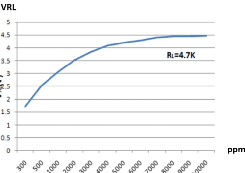
The manufacturer provides sensitivity curves showing the gas concentration against the ratio of the sensor resistance to the resistance in clean air.
MQ-7
This is a semiconductor based carbon monoxide sensor that can be used for sensing CO concentrations in the air. The sensor has high sensitivity and fast response and can detect CO gas concentrations from 20 to 2000ppm. The sensor provides an analog output in the form of resistance. The use of the sensor is simple and it requires a heater coil to be powered with 5V and a load resistance to be connected across its output terminals and to an ADC converter. The value read from the sensor is proportional to the CO concentration.

MQ-4
This semiconductor sensor can be used for sensing natural gasses, mainly the methane (CH4) concentrations in the air. The gas concentrations from 200 to 10000ppm can be detected by the sensor. As with the MQ-7, an internal heater is used and the sensor’s output is an analog voltage which is proportional to the ambient gas concentration. An ADC is required to read and process the sensor’s output. MQ-4 is commonly used in domestic and industrial flammable gas detection applications.
MQ-6
This sensor is used to detect liquefied petroleum gas (LPG) concentrations in the air, which is mainly composed of propane and butane. The sensitive material of the sensor is SnO2 whose conductivity changes when exposed to LPG gasses. The sensor can detect gas concentrations in the range from 200 to 10000ppm. As with the other sensors, an internal heater is used and the sensor provides an analog output voltage proportional to the ambient gas concentration.
MQ-8
This sensor can be used to detect hydrogen gas concentrations in the range 100-10000ppm. The operational principle of the sensor is same as the others where an internal heater is used and the analog output voltage is proportional to the ambient hydrogen gas concentration.
MQ-3
This sensor is suitable for detecting alcohol concentration in the breath and is commonly used in hand-held breathalyser devices to test the alcohol level of drivers. The sensor requires a heater voltage and provides an output voltage proportional to the sensed alcohol concentration.
MICS-2700
This sensor is a 4-pin semiconductor device used to detect the concentrations of the NO2 gas in the range 0.05 to 5ppm. The measurement is done with a heater power of 43mW which raises the temperature of the sensing resistor to about 220ºC.
Designing a wireless gas detection & monitoring system
Gas detection systems are life-saving devices as they detect the presence of toxic gasses and alert the people to leave the area. Such devices are recommended to be used in every home and in public places such as in schools, hospitals, train station, airports, and so on.
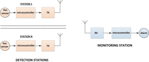
In this section the design of a microcontroller based wireless LPG gas detection and monitoring system is given. The system described here is multi-node and is therefore suitable for use in places like caravan sites, holiday homes, students’ halls of residence, old peoples’ homes, university campus, and other places where groups of people live and large number of detectors may be required. The block diagram of the designed system is shown in below.
The system consists of two parts: gas detection stations, and gas monitoring station. A gas detection station consists of a semiconductor gas sensor, a microcontroller that receives signals from the gas sensor and activates a suitable transmitter module to send a message to the monitoring station together with the unique ID of the station to alert that gas leakage has been detected at the specified station. Appropriate action is then taken at the monitoring station such as sounding an alarm and attending the requesting station for help. In this design up to 16 stations can be used in the system with their unique IDs selected with switches and ranging from 0 to 15.
Both the detection stations and the monitoring station use low-cost 8-bit medium performance PIC18F family of microcontrollers. The hardware details of each station are given below.
Detection Stations
The MQ-6 semiconductor LPG gas sensor chip is used in the design since it is highly sensitive, low-cost and is easy to use. LPG concentrations above 1000ppm are accepted to be toxic and should be avoided. The system has been designed so that it is activated if the LPG concentration is sensed to go above 1000ppm.
The MQ-6 pins are organised in groups of three pins on each side of the sensor where pins 2 and 5 are the heater pins, and 1,3 and 4,6 are the sensor circuit pins.
A load resistor RL is connected in series with sensor resistance Rs to convert the resistance Rs to a voltage. Shown below is the sensor output voltage when a 4.7K load resistor is used.
The circuit diagram of a detection station is shown below. A PIC18F2550 type microcontroller is used in the design with an external 8MHz crystal. The PLL clock multiplier is used to increase the operating clock frequency from 8MHz to 48MHz. The sensor output is connected to a 10K variable resistor which feeds into analog input channel RA1 of the microcontroller. The sensitivity of the device can easily be adjusted via this potentiometer. Whenever a gas leakage is detected, a message is sent to the monitoring station together with the unique station ID.
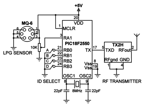
Every station is assigned a unique ID by using the switches connected to PORTB. In this design 4 switches are used, making it possible to have up to 16 detection stations (0 to 15).
Depending upon the applications the distance between the detection stations and the monitoring station could be hundreds of meters or even more. For example, in a large caravan site this distance could even be a few kilometres. For this reason, it was decided to use RF transmitter and receiver modules in the design.
The Radiometrix TX2H transmitter module was found to be suitable for use in the design. This is a 433.92MHz UHF FM transmitter module with a power output of 25mW, having a typical range of 500 metres, consuming only 23mA of current. Radiometrix is a leading designer and manufacturer in UK of professional grade VHF and UHF low power radio modules according to the international FCC/ETSI standards. A large selection of transmitter, receiver, and transceiver modules and associated products are available from transmit powers of 5mW to 500mW.
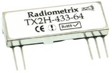
TX2H is pin compatible with the lower power TXL2 and the higher power TX2EH, and therefore compatible longer or shorter range transmitter modules can be used without having to change the hardware or the software of a station. The module is powered from the +5V supply and is connected to UART output (TX) of the microcontroller. A helical, loop, or a whip antenna can be used with the module. The length of the whip antenna should be 16.4cm total from the RF pin. The pin configuration of TX2H is shown in Table 1. The gas detection stations can be powered from +5V mains adapters, usually used to charge mobile phones.
| TX2H pin | Name | Function |
| 1 | RF gnd | RF ground |
| 2 | RF out | 50 ohm RF output to antenna |
| 3 | VCC | + 5V DC supply input |
| 4 | GND | DC supply ground |
| 5 | TXD | Transmit data input |
Monitoring Station
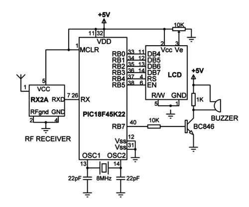
Shown below is the circuit diagram of the monitoring station. In this design a PIC18F45K22 microcontroller is used with an LCD display and a buzzer. The microcontroller is clocked using 8MHz crystal. Although a microcontroller is used in this design, in large systems it may be preferable to use a PC instead.
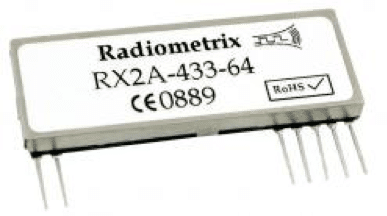
A compatible RX2A UHF receiver module is used at the monitoring station. This module has a receive sensitivity of -108dBm and operates with power supply from 2.7V to 16V. The typical current consumption is 11.6mA. The use of the module requires the connection of an external antenna. The received data pin is connected to the UART input (RX) of the microcontroller. Below table gives the pin configuration of the RX2A.
| TX2H pin | Name | Function |
| 1 | RF in | 50 ohm input from the antenna |
| 2 | RF gnd | RF ground |
| 3 | RSSI | Received signal strength |
| 4 | GND | DC supply ground |
| 5 | VCC | DC power supply |
| 6 | AF out | Analog output from the FM demodulator |
| 7 | RXD | Received data input |
Software
The software of the system has been developed using the mikroC Pro for PIC language, compiler, and the IDE developed by mikroElektronika (www.mikroe.com). mikroC is a standard C compatible language developed specifically for the PIC microcontrollers and has a rich library of functions including RS232, SPI, I2C, LCD, GLCD, TFT, SD card, PWM and many more.
Detection Station Software
The software listing of a detection station is given below. At the beginning of the program the threshold is set to 2500mV so that the system is activated when the LPG concentration level is approximately above 800ppm. Then PORTB is configured as digital input and RA1 is configured as analog input. PORTB internal pull-ups are enabled and the UART is initialized to operate at 9600 baud. The remainder of the program executes in an endless loop. Inside this loop, the sensor output is read and converted into millivolts. If the sensor output is greater than 2.5V then the station ID is read and the message ID=nn/ is sent to the monitoring station. Here nn is the station ID and character “/” is the terminator of data. The program repeats after one minute delay.
/************************************************************************
GAS MONITOR STATION
===================
This is the software for the gas detector station. The system is built using the following components:
PIC18F2550 microcontroller (with 8MHz crystal, and 2x22pF capacitors)
MQ-6 LPG gas sensor chip
10K potentiometer
4-way switch
Radiometrix TX2H RF transmitter module
A gas detector station detects the presence of LPG gas and sends a message to the gas monitoring station together with the station ID to alert that gas has been detected.
Author: Dogan Ibrahim
Date: July 2016
Program: Detector.c
************************************************************************/
void main()
{
unsigned int ADC;
unsigned char ID, Msg[10]= “ID=”;
unsigned char Txt[4];
float mV;
float threshold = 2500.0; // Threshold (in mV)
ADCON1 = 0x0D; // RA1 analog, PORTB digital
TRISA = 2; // RA1 is input
TRISB = 0x0F; // RB0-RB3 are inputs
INTCON2.RBPU = 0; // Enable PORTB pull-ups
UART1_Init(9600); // Initialize UART
while(1) // Do Forever
{
ADC = ADC_Read(1); // Read LPG Sensor
mV = ADC*5000.0 / 1024.0; // Analog sensor voltage
if(mV > Threshold) // If > 2.5V
{
ID = PORTB; // Read PORTB data
ID = ID & 0x0F; // Extract low nibble
if(ID > 9) // If ID > 9
{
Txt[0] = ID / 10;
Txt[1] = ID – 10*Txt[0] + ‘0’; // Convert to string
Txt[0] = Txt[0] + ‘0’; // Convert to string
}
else // If ID <= 9
{
Txt[0] = ‘0’;
Txt[1] = ID + ‘0’; // Convert to string
}
Txt[2] = ‘/’; // Insert terminator
Txt[3] = 0x0; // Insert NULL
strcat(Msg, Txt); // Combine ID= with ID number
UART1_Write_Text(Msg); // Send Msg to UART
Delay_Ms(60000); // Wait 1 minute and repeat
}
}
}
Software listing of the detection station
Monitoring Station Software
The software listing of the monitoring station is given below. At the beginning of the program the interface between the LCD and the microcontroller is defined and PORTB and PORTC are configured as digital ports. Then the UART is initialized to 9600 baud and the LCD is initialized. The program then enters an endless loop where inside this loop the program waits until data is received from a detection station, terminated with the “/” character. After receiving valid data the station ID of the station is displayed and the buzzer is activated. The program repeats after one minute delay.
/************************************************************************
GAS MONITOR STATION
===================
This is the software for the gas monitoring station. The system is built using the following components:
PIC18F45K22 microcontroller (with 8MHz crystal, and 2x22pF capacitors)
2×16 character LCD
Buzzer (with BC846 transistor switch)
Radiometrix TX2A RF receiver module
The gas monitoring station receives messages from the detection stations when gas leakage has been
detected and it displays a message on the LCD giving the station ID and also activating the buzzer.
Author: Dogan Ibrahim
Date: July 2016
Program: Monitoring.c
************************************************************************/
#define BUZZER PORTB.RB7
// LCD pinout settings
sbit LCD_RS at RB4_bit;
sbit LCD_EN at RB5_bit;
sbit LCD_D7 at RB3_bit;
sbit LCD_D6 at RB2_bit;
sbit LCD_D5 at RB1_bit;
sbit LCD_D4 at RB0_bit;
// LCD pin direction
sbit LCD_RS_Direction at TRISB4_bit;
sbit LCD_EN_Direction at TRISB5_bit;
sbit LCD_D7_Direction at TRISB3_bit;
sbit LCD_D6_Direction at TRISB2_bit;
sbit LCD_D5_Direction at TRISB1_bit;
sbit LCD_D4_Direction at TRISB0_bit;
void main()
{
unsigned char Txt[10];
unsigned char ID;
ANSELB = 0; // PORTB is digital
ANSELC = 0; // PORTC is digital
TRISB = 0;
LCD_Init(); // Initialize LCD
UART1_Init(9600); // Initialize UART
while(1) // Do Forever
{
Lcd_Cmd(_LCD_CLEAR); // Clear LCD
BUZZER = 0; // Stop the buzzer
if(UART1_Data_Ready() == 1) // If data received
{
UART1_Read_Text(Txt, “/”, 255); // Read until the terminator
if(Txt[0] == ‘I’ && Txt[1] == ‘D’ && Txt[2] == ‘=’) // IF ID found
{
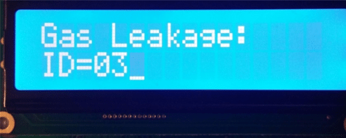
Lcd_Out(1,1,”Gas Leakage:”); // Display message
Lcd_Out(2,1,Txt); // Display station ID
BUZZER = 1; // Activate buzzer
Delay_Ms(60000); // Wait 1 minute
}
}
}
}
Software listing of the monitoring station