A rain alarm, also known as a rain sensor or rain alarm system, is a device that can have various utilities depending on its design and intended use.
Here are some common uses and benefits of a musical rain alarm:
1. Irrigation Control: Many agricultural and landscaping systems use rain alarms to automatically turn off irrigation systems when it rains. This conserves water and prevents overwatering, which can be harmful to plants.
2. Automated Window Closure: Some rain alarms are integrated into smart home systems to close windows and skylights when it starts to rain automatically. This can help prevent damage due to rain-water and maintain indoor comfort.
3. Rainfall Monitoring: In meteorology and hydrology, rain alarms are used to monitor and record rainfall data. This information is critical for weather forecasting, flood prediction, and water resource management.
4. Outdoor Event Planning: For outdoor events like weddings, concerts, and sports games, a musical rain alarm can be used to monitor the weather. It can trigger an alert or music to warn event organizers and participants of impending rain so they can take appropriate action.
5. Vehicle Alert: In some cases, rain alarms can be installed in vehicles to provide drivers with real-time information about rain intensity. This can be useful for making driving decisions and enhancing safety.
6. Gardening: Gardeners often use rain alarms to track rainfall and watering needs. They can set up automated watering systems that are triggered by the rain alarm data.
7. Roof leak detection: Rain alarms can be installed in attics to detect roof leaks. If water starts to enter the attic due to a leaky roof, the alarm can alert homeowners to the issue.
8. Conservation: Rain alarms can encourage water conservation by signaling when rain is falling, prompting individuals to turn off faucets, sprinklers, and other water-consuming devices.
9. Pool maintenance: For pool owners, rain alarms can help manage water levels. When it rains, they can be programmed to automatically drain excess water from the pool to prevent overflows.
10. Educational purposes: Rain alarms are sometimes used in educational settings to teach students about weather and climate concepts, such as precipitation measurements and data collection.
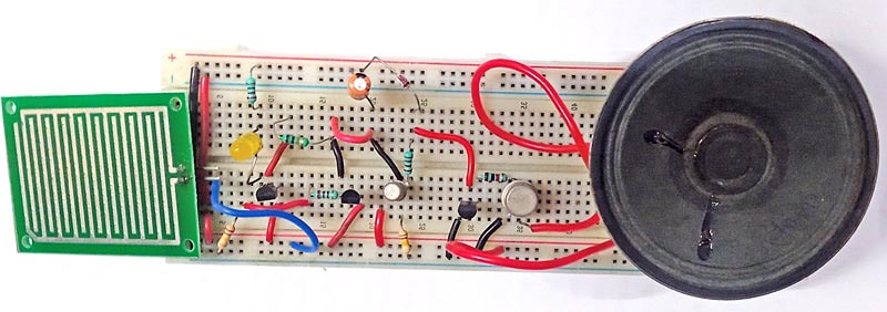
The utility of a musical rain alarm depends on its specific application and how it is integrated into various systems and processes. The author’s prototype is shown in Fig. 1.

| Rain Alarm Parts List | |
| Semiconductors: | |
| IC1 | -LM7805, 5V voltage regulator |
| IC2 | -UM66 melody generator |
| T1 | -BC547 NPN transistor |
| T2 | -BC548 NPN transistor |
| T3 | -2N2219 NPN transistor |
| T4 | -SL100 NPN transistor |
| BR1 | -1A bridge rectifier |
| LED1 | -5mm red LED |
| LED2 | -5mm yellow LED |
| Resistors (all 1/4-watt, ±5% carbon): | |
| R1 | -1-kilo-ohm |
| R2 | -220-kilo-ohm |
| R3, R4, R7 | -220-ohm |
| R5, R8 | -10-kilo-ohm |
| Capacitors: | |
| C1 | -1000μF, 35V electrolytic |
| C2 | -1000μF, 16V electrolytic |
| C3 | -220μF, 16V electrolytic |
| Miscellaneous: | |
| CON1, CON2 | -2-pin connector |
| LS1 | -8Ω, 0.5-watt speaker |
| X1 | -230V AC primary to 9V, 500mA secondary transformer |
| RS | -Rain sensor |
Rain Alarm Circuit
The circuit diagram of the musical rain alarm is shown in Fig. 2. The heart of this device is a rain sensor connected across CON2. The circuit comprises step-down transformer X1, bridge rectifier BR1, 5V voltage regulator LM7805 (IC1), rain sensor (RS), four NPN transistors (T1 through T4), melody generator UM66 (IC2), speaker (LS1), 3.1V zener diode, and a few other components.

This device operates with 5V DC, which is derived from the 230V AC primary to 9V, 500mA step-down transformer X1. The 230V AC Mains is connected to the primary of X1 via CON1 in the circuit. The secondary of X1 is at 9V AC, which is connected to the bridge rectifier BR1 for rectification and filtered by capacitor C1. The rectified 5V is given to the rain sensor and the circuit to operate.
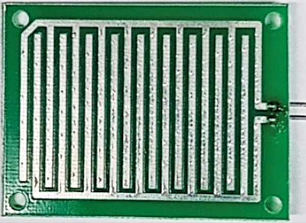
In this circuit, we are interfacing a musical rain sensor with the melody IC UM66. We have used two LEDs in the circuit; one (LED1) is for the power supply indicator, and the second (LED2) is yellow, indicating that rain is continuing. Fig. 3 shows the image of the rain sensor used here. It has two terminals that need to connect across CON2 during installation.

Working
When the rain starts, the sensor provides a positive voltage at point ‘B,’ which makes transistor T2 to conduct. The capacitor C2 then charges and transistor T3 conducts; IC2 gets 3.1V to enable the melody generator sound via transistor T4 and the speaker. At the same time, transistor T1 also conducts, and the yellow LED glows to indicate the status of rain.
Rain Alarm Circuit PCB Design
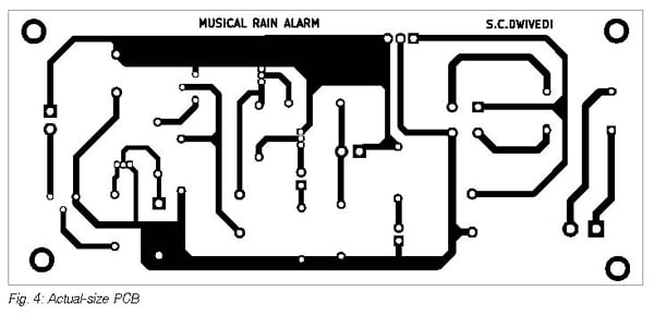
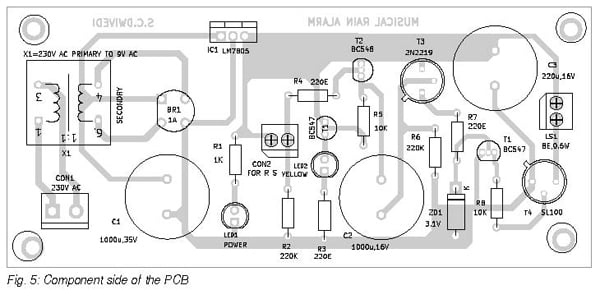
An actual-size, single-side PCB layout for the musical rain alarm is shown in Fig. 4, and its component layout is shown in Fig. 5. After assembling the circuit on the PCB, enclose it in a suitable box. Fix LED1, LED2, and CON2 on the front side of the box and the mains power connector CON1 on the rear side of the box.


Connect two pins of the rain sensor with twin wires and install it on the roof in such a way that raindrops should fall on it. Connect the other ends of the twin wires to CON2 on the PCB.
Bonus: You can watch the video of the tutorial of this DIY project at https://www.electronicsforu.com/videos-slideshows/live-diymusical-rain-alarm
S.C. Dwivedi is an electronics enthusiast and circuit designer at EFY


