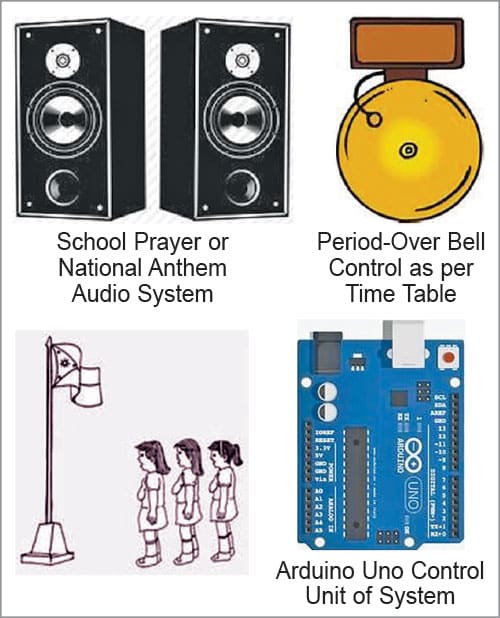
This school automation system for reminding the school prayer or national anthem time and period-over bell utilises Arduino to automate the bell schedule and integrate the playing of the national anthem in schools or institutes.
The system comprises an Arduino microcontroller, an RTC DS3231 module, a microSD card module, and an audio jack to connect the speaker.
POC Video Tutorial In English
POC Video Tutorial In Hindi
Fig. 1 illustrates the core functionality of this system, which eliminates the need for manual bell ringing, ensures smooth transitions between periods, and reduces the administrative burden on school staff. The components required for constructing this school automation system are listed in Table 1.

| Table 1: Bill of Materials | ||
| Components | Quantity | Description |
| Arduino Uno | 1 | Control unit of project |
| RTC 3231 | 1 | Real time clock |
| Microcard SD module | 1 | For store audio track |
| 5V battery/power bank | 1 | 5V |
| 3.5mm audio female connector | 1 | To interface the speaker |
Software
The logical software is written in Arduino IDE. After installing the related libraries, including Wire.h for I2C communication, SD.h for SD card interfacing, and TMRpcm.h for audio playback, upload the code.
Before uploading the given sketch to the Arduino Uno board, ensure that the correct board is selected. After selecting the port, upload the sketch file ‘code.ino’ to the board. Fig. 2 shows a screenshot of the source code.


The provided Arduino program is designed to automate the ringing of a school bell and play school prayer or national anthem at preset times. It uses various libraries and hardware components to achieve this functionality:
1. RTC (real-time clock): Keeps track of the current time, even when the Arduino is powered off. It ensures the system operates on the correct schedule
2. SD card module: Stores audio files, including the prayer or national anthem, to be played through a speaker
3. TMRpcm library: Handles audio playback from the SD card
4. Buzzer: Emits a sound at the start and end of each period to signal the change
Algorithm
1. Initialisation
• Set up serial communication for debugging
• Initialise the SD card and check for successful initialisation
• Initialise the RTC and set the current time, if needed (commented out in the code)
• Set up the TMRpcm library for audio playback and configure the speaker pin
• Set up the buzzer pin
2. Main loop
• Get the current time from the RTC
• Check the current time against preset times for the prayer or national anthem and each period bell
• If the current time matches a preset time, play the audio or sound the buzzer
• Use a delay to avoid busy-waiting and reduce CPU usage
Detailed Code Explanation
1. Initialisation
Serial.begin(9600): Initialises serial communication at a baud rate of 9600 for debugging
SD.begin(SD_CS_PIN): Initialises the SD card. If it fails, a message is printed
Wire.begin(): Initialises I2C communication for the RTC
rtc.begin(): Initialises the RTC. If it fails, a message is printed
tmrpcm.speakerPin = AUDIO_OUT_PIN: Sets the pin for audio output
tmrpcm.setVolume(5): Sets the volume level
pinMode(buzzer_pin, output): Sets the buzzer pin as an output
2. Main loop explanation
rtc.now(): Gets the current time from the RTC
Serial.print(): Prints the current time to the serial monitor for debugging
digitalWrite(buzzer_pin, low): Ensures the buzzer is off initially
Time checks: Checks if the current time matches any of the preset times. If a match is found
playAudio(): Plays the prayer or national anthem, if it is the starting time
digitalWrite(buzzer_pin, high): Turns on the buzzer
delay (30000): Keeps the buzzer on for 30 seconds.
digitalWrite(buzzer_pin, low): Turns off the buzzer
delay (1000): Adds a delay of one second
School Automation System – Circuit and Working
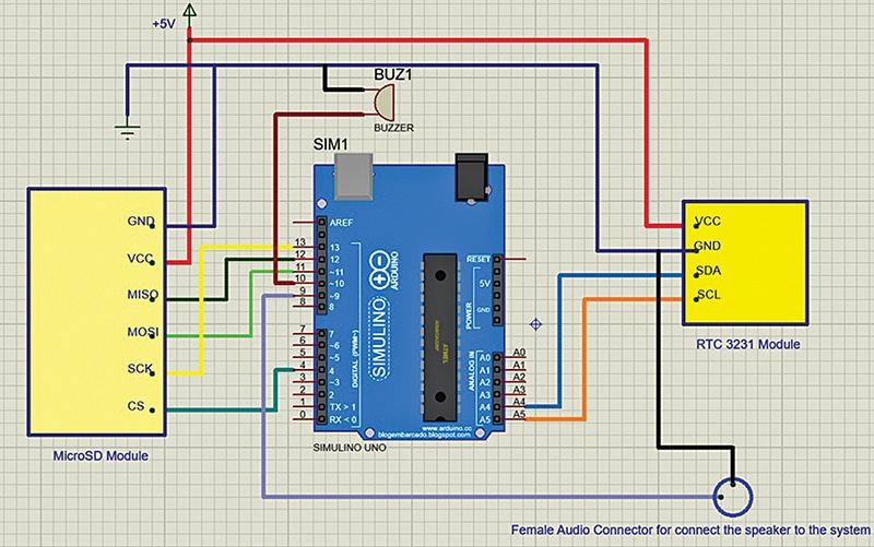
Fig. 3 shows the circuit diagram of the automation system. It consists of Arduino Uno, real-time clock, microcard SD module, and 3.5mm audio female connector. The Arduino program is designed to automate the ringing of bells and playing of audio files according to a predefined schedule.
It utilises various libraries, including Wire.h for I2C communication, SD.h for SD card interfacing, TMRpcm.h for audio playback, and RTClib.h for real-time clock functionality.
The setup function initialises serial communication, SD card, RTC module, TMRpcm library, and sets the volume level. It also configures the buzzer pin as an output. In the loop function, it continuously reads the current time from the RTC module and checks if it matches any of the predefined time intervals for bell ringing.
If a match is found, it triggers the buzzer, plays the audio file (if available), and then waits for a specified duration before turning off the buzzer.
Microcard SD module: The pins on an SD card module serve the following functions:
- VCC: This pin provides power to the SD card module. It is usually connected to a 5V or 3.3V power source, depending on the module’s specifications
- GND: This pin is the ground connection, providing the reference voltage for the module
- MISO (master in slave out): This pin is used for data transfer from the SD card to the microcontroller or other device. It carries data from the SD card to the microcontroller when reading data
- MOSI (master out slave in): This pin is used for data transfer from the microcontroller to the SD card. It carries data from the microcontroller to the SD card when writing data
- SCK (serial clock): This pin is the clock signal generated by the microcontroller for synchronising data transfer between the microcontroller and the SD card
- CS (chip select): This pin is used to enable communication with the SD card. When this pin is set to low (usually connected to ground), it indicates to the SD card that it should listen to commands from the microcontroller. The playAudio function is called to play the audio file stored on the SD card when a bell ringing event occurs
Real-time clock (RTC) module: The real-time clock (RTC) module typically consists of several pins, each serving a specific function:
- VCC: This pin is connected to the power supply (usually 5V or 3.3V) to provide power to the RTC module
- GND: This pin is connected to the ground (0V) of the power supply to complete the circuit
- SDA (serial data): This pin is used for bidirectional serial data transfer between the RTC module and the microcontroller. It carries data between the microcontroller and the RTC module during communication
- SCL (serial clock): This pin is used to synchronise the data transfer between the microcontroller and the RTC module. It generates clock pulses for timing the serial communication
- SQW (square wave output) not connected: This pin outputs a square wave signal with a frequency specified by the RTC module. It can be used as an interrupt signal or for other timing-related purposes
- 32kHz output not connected: Some RTC modules may have an additional pin for outputting a 32kHz clock signal, which can be used for timekeeping or other timing-sensitive applications. These pins allow the RTC module to communicate with and be controlled by the microcontroller, enabling accurate timekeeping and other time-related functions in embedded systems
Construction and Testing
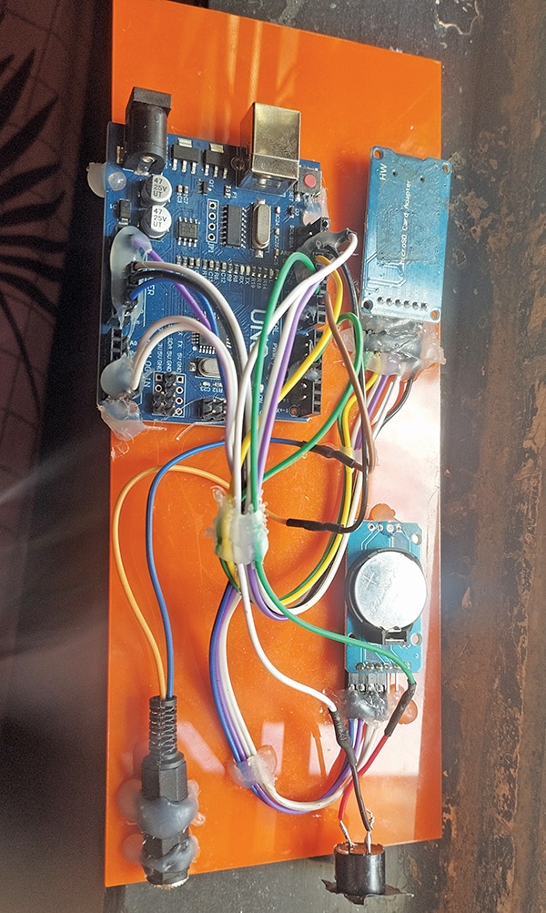
For the construction of the device, first upload the source code `code.ino` into the Arduino Uno board. Then assemble all the components according to the circuit diagram as shown in Fig. 3 and Tables 2 and 3. The author’s prototype is shown in Fig. 4.
| Table 2: Connecting components MicroSD | |
| Arduino Pins | Pins MicroSD Module and Buzzer |
| Arduino pin 4 | CS (chip select) pin-6 |
| Arduino pin 9 | Positive pin of audio female connector |
| Arduino pin 10 | Connected to positive pin of buzzer |
| Arduino pin 11 | Connected to MOSI pin-4 (master out slave in) |
| Arduino pin 12 | Connected to MISO pin-3 (master in slave out) |
| Arduino pin 13 | SCK-pin-5 (serial clock) |
| Table 3: RTC module connection | |
| RTC Module | Arduino Pins |
| SDA | Connected to Arduino analogue pin-A4 |
| SCL | Connected to Arduino analogue pin-A5 |
| Vcc | Connected to Arduino analogue pin-A5 |
| GND | Connected to Arduino GND pin |
After proper assembly of the device, the call bell is ready to work as follows:
Initially, the circuit is powered up with a 12V external power supply. When school starting time arrives, an announcement for the prayer or national anthem will play.
After that, the bell will ring immediately to indicate the start of school.
At the end of the first period (as per the set time in the program), the bell will ring, indicating the end of the first period and the start of the second period.
Similarly, the designed circuit will track the end of each period and ring the bell accordingly. Repeat from step 1.
As an improvement, the bell sound can be replaced with an audio announcement after each period, where the period number is mentioned.
Nilesh Ramesh Thakre is Head of the Department at SNJB’s Shri H.H.J.B Polytechnic Chandwad, Dept. of Electronics and Telecommunication Engineering