
Obstacle detection is one of the major concerns for a fully or a partially blind person (e.g. person suffering from night-blindness, cataracts, glaucoma, albinism or injury). Presented here is a smart stick using Arduino Uno. The stick uses Ultrasonic sensors for obstacle detection. The main aim of this project is to detect nearby obstacle and notify the user of the direction of that obstacle, thereby enabling the user to determine the corrective direction to head.
List of components
| Microcontroller | |
| Development Board | Arduino Uno |
| Ultrasonic transceivers | |
| SNR1 | HC-SR04 |
| SNR2 | HC-SR04 |
| SNR3 | HC-SR04 |
| Buzzers and Vibrators | |
| SND1 | Piezo-electric buzzer |
| SND2 | Vibrating motor |
| Switches | |
| S1 | Toggle switch |
Circuit & Working
Circuit shown below operates using a minimum of 5V DC power supply (Across Vcc & GND pin of Arduino UNO). The Arduino itself requires only 5V to operate but considering the fact that it has to power three ultrasonic sensors, one piezo-electric buzzer & a vibrating motor we have used a 9V supply. Arduino has an inbuilt 5V voltage regulator so we also have the options to power it using a 6V or 12V supply.
The brain of the circuit is Arduino Uno MCU board (Board1). Three Ultrasonic sensors “HC-SR04” are used for obstacle detection using ultrasonic waves. These sensors require a power supply of 3.3V each to operate up to a distance of 3 m and can detect obstacles within an average angle of 25 degrees in the sphere.
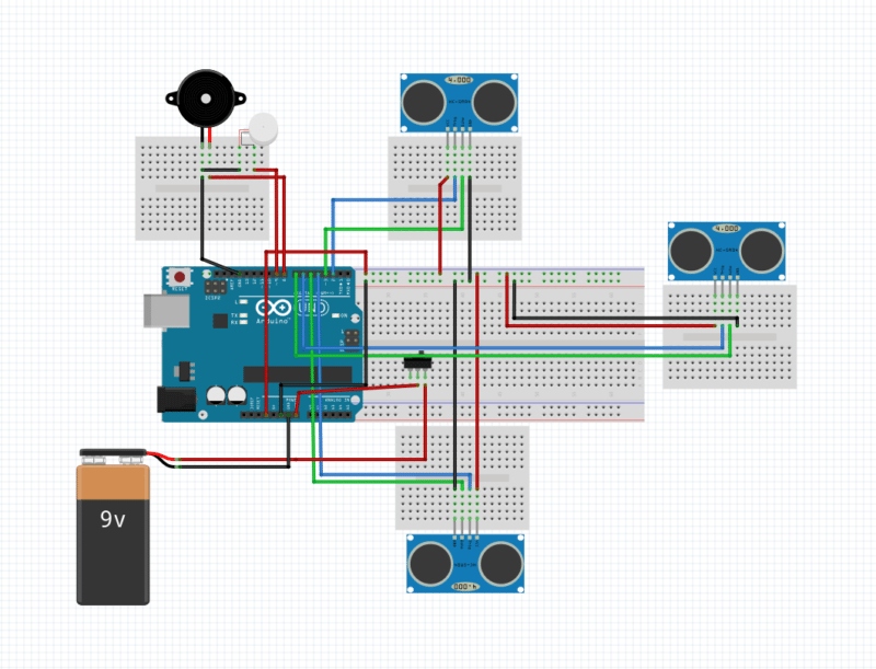
Two of the four pins of these three sensors namely Vcc & GND are connected to Arduino’s 3.3V power output. The remaining two pins – TRIG & ECHO are connected to Arduino as follows.
| Sensor No. | Trig | Echo |
| SNR1 | 2 | 3 |
| SNR2 | 4 | 5 |
| SNR3 | 6 | 7 |
Apart from this, a peizo-electric buzzer SND1 and a vibrating motor SND2 are connected so that it can guide the user using different tones and vibration. Also, a toggle switch, S1 is used to save the power when the device is not in use or when the impaired person has support of others to guide him/her.
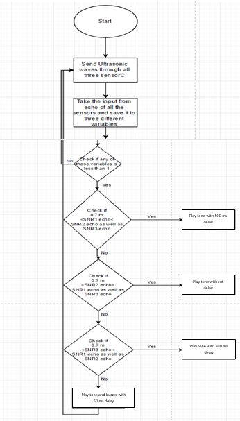
The Arduino is programmed in such a way that on switching ‘ON’ the Arduino, it sends a LOW to HIGH signal on the TRIG pin of all the three Ultrasonic sensors. These ultrasonic sensors will send an Ultrasonic wave using the ultrasonic transmitter of the sensor. These ultrasonic waves travel through air and on colliding with an obstacle, get reflected back. Programming is done in such a manner, that when this obstacle is in the range of 1.4 m of the sensor, the Arduino will play the buzzer with different delay for obstacles located on the sides, and no delay for the straight ones. To further enhance its performance, if the obstacle is too close (less than 0.7 m from sensor) then the vibrating motor is also activated.
The sensor would give an electrical response at the ECHO pin of the sensor. This response is the time taken by the wave for a round journey from sensors to obstacle and back to the sensors. For our calculation, we need only the one-way distance. This can be calculated by Arduino using the following formula:
Here, Duration = Echo output;
and since we need only one-way distance, hence we divide this duration by 2.
Here the constant 29.1 is derived as follows:
- The speed of sound is 343.5 m/s or 0.0345 cm/microseconds.
- 1/0.0345 cm/microseconds is 29.1 microseconds/cm.
- Dividing the Duration (ms) by 29.1 (microseconds/cm) gives us the distance in (cm).
To distinguish between the direction of obstacle location, the following mechanism is followed:
- For Left and Right side direction locations, the delay is 500 ms.
- For Forward direction location, the delay is zero.
An additional provision of a motor that vibrates the stick is planted into the assembly for very near obstacles. Experimentation study shows the optimum distance post assembly, to be 0.7m.
Construction and Testing
Implementation of the circuit on a printed circuit board is not going to be fruitful, as most of the circuit parts would be implemented on a wooden chassis/cardboard/plastic mounting. We can’t hardwire the sensors on PCB as they would be in a vertical position; and more so placed in a circular /semi-circular fashion. The final assembled device is placed about midway on the stick. Once the circuit is assembled, test the circuit at the test points given in table below.
| Test points | Details |
| TP0 | 3.3V |
| TP1-TP3 | 3.3V |
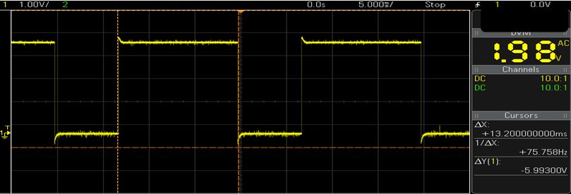
| TP4-TP6 | Waveform 1 |
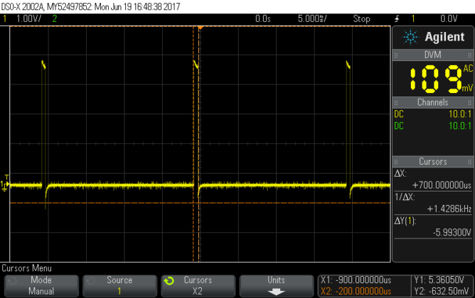
| TP6-TP9 without any obstacle | Waveform 2 |
| TP6-TP9 with obstacle | Waveform 3 |
After that, make a cardboard box or a plastic box with 8 circular holes in it. 6 of the 8 holes should be of the size of transmitter/receiver of the ultrasonic sensors & they should be punched on the wall of the box. Remaining 2 holes should be of the size greater than the diameter of the wooden stick you choose & they should be punched on the top & bottom of the box, also they should be collinear to each other. The top of the box should be removable if in case we need the access to circuit. Consider below figure for reference.
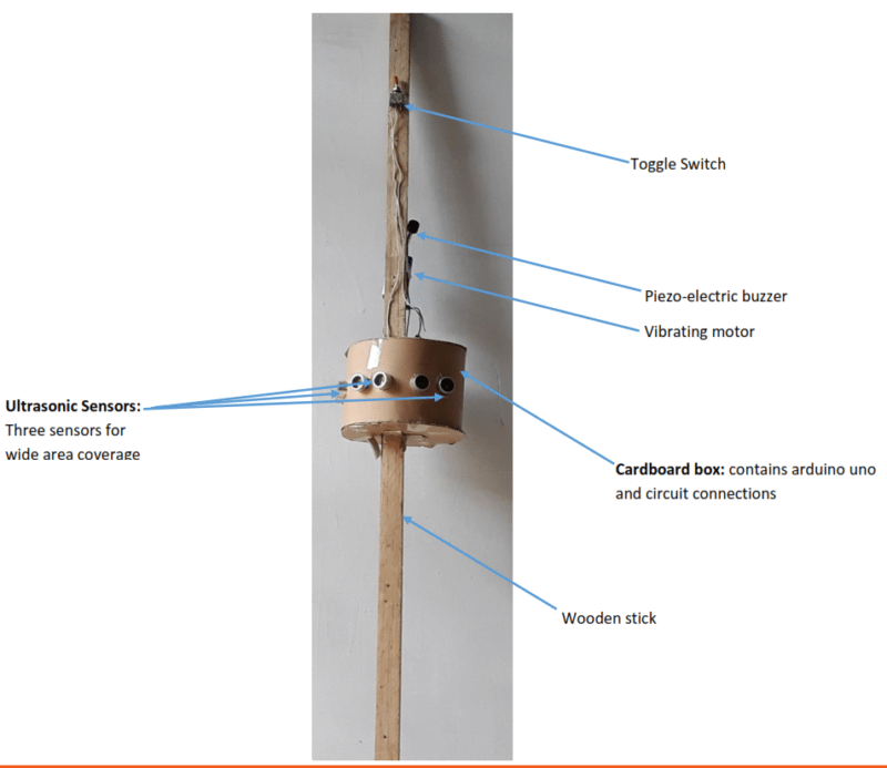
Once the circuit is assembled, put the Arduino & sensor along with the connecting wires inside the cardboard box. Through the six holes punched on the surface take the transmitter & receiver set of each sensor out of the box. The significance of this assembly is to avoid false triggers as the box itself would behave as an obstacle to the sensors. Proper placing and alignment is very important. Ensure proper mounting by optimally placing the buzzer, vibration motor, switch & battery after removing it from the box. Test the assembly now against variable obstacles at variable distances.
Flow Chart
The flowchart for the program is given below.
Software
Arduino version 1.6.6 is used for this project but as no directory change is made, the same can be achieved using any of the latest versions of the Arduino IDE. The IDE is available here.
The next section gives a brief insight into the pin definitions and input-output port details.
[stextbox id=’grey’ caption=’Defining the pins and variables in the program’]#define trig1 3
#define echo1 2
#define trig2 4
#define echo2 5
#define trig3 7
#define echo3 8
#define motor 12
#define buzzer 11
long duration1,distance1,duration2,distance2,distance3,duration3;[/stextbox]
[stextbox id=’grey’ caption=’Defining which pins to be used as Input or Output’]void setup()
{
pinMode(trig1, OUTPUT);
pinMode(echo1, INPUT);
pinMode(trig2, OUTPUT);
pinMode(echo2, INPUT);
pinMode(trig3, OUTPUT);
pinMode(echo3, INPUT);
pinMode(motor, OUTPUT);
pinMode(buzzer, OUTPUT);
}[/stextbox]
[stextbox id=’grey’ caption=’Initialize ultrasonic waves via sensors and interfacing I/P ports to corresponding variables:’]void loop()
{
//For sensor 1
digitalWrite(trig1, LOW);
delayMicroseconds(2);
digitalWrite(trig1, HIGH);
delayMicroseconds(10);
duration1 = pulseIn(echo1, HIGH);
//For sensor 2
digitalWrite(trig2, LOW);
delayMicroseconds(2);
digitalWrite(trig2, HIGH);
delayMicroseconds(10);
duration2 = pulseIn(echo2, HIGH);
//For sensor 3
digitalWrite(trig3, LOW);
delayMicroseconds(2);
digitalWrite(trig3, HIGH);
delayMicroseconds(10);[/stextbox]
[stextbox id=’grey’ caption=’Calculate the distances and save them to variables.’]distance1 = (duration1/2)/29.1;
distance2 = (duration2/2)/29.1;
distance3 = (duration3/2)/29.1;[/stextbox]
[stextbox id=’grey’ caption=’Calculate the distances and save them to variables.’]if ( distance1 < 120 || distance2 < 120 || distance3 < 120 )
{
if ( distance1 <= 60 || distance2 <= 60 || distance3 <= 60 )
{
digitalWrite(buzzer, HIGH);
digitalWrite(motor,HIGH);
delay(50);
digitalWrite(buzzer,LOW);
digitalWrite(motor,LOW);
delay(50);
}[/stextbox]
Following are the criteria to activate either the buzzer or the motor or both.
| Distance | Operation |
| For distance > 1.4m | No Buzzer |
| For 0.7m < distance < 1.4m | Buzzer |
| distance < 0.7m | Buzzer + Vibration |
For the convenience of the user, apart from the buzzer a vibrating motor informs the user of a nearby obstacle in the corresponding direction as well.
[stextbox id=’grey’ caption=’apart from the buzzer a vibrating motor informs the user of a nearby obstacle in the corresponding direction ‘]else if ( distance1 > 60 && distance1 < distance2 && distance1 < distance3 )
{
digitalWrite(buzzer, HIGH);
delay(500);
digitalWrite(buzzer,LOW);
delay(500);
}
else if ( distance2 > 60 && distance2 < distance1 && distance2 < distance3 )
{
digitalWrite(buzzer, HIGH);
delay(500);
digitalWrite(buzzer,LOW);
delay(500);
}
else if ( distance3 > 60 && distance3 < distance2 && distance3 < distance2 )
{
digitalWrite(buzzer, HIGH);
}
}
digitalWrite(buzzer,LOW);
}[/stextbox]



The ultrasonic sensor that’s being used would detect out distances for a particular height out wrt ground. For low height obstacles like stairs , an ir sensor may be used with some low tone output from the piezo buzzer.
The only dillema in the application i am thinking of is that ir would work out well in case of going upstairs, but how could we make it work for downward operation.
For down operation he/she can use the stick itself,or u can use a tilted ir sensor,if nothing detected means there is downstairs or somethng
I may need your help again.
Since arduino has a 5 v supply which could be provided oyt by another 6-12 V form external sources,
can you tell me how to use multiple sensors at once?
As only 1 sensor draws out full 5 V for operation and in my design, there are 3 us sensors, 1 infrared, 1 buzzer and 2 vibrational motors?/
Kindly help me, i have to deliver the project withing next 20 days
u can put external lm7805 regulator with the 9v battery then u will get constant voltage to all the sensors
I am the guide of this working project. Shreyansh, Hope you could deliver the project. LM 7805 should have worked as suggested by Pavan rebel.
ma’am can u please share on which software the testing was done?
This project is a successful tried and tested working module.
For queries related to this and other related parameters, feel free to contact me: [email protected]
Where I can find Arduino code for the project mentioned above….
Hello Aayush,
You have to try it on our own.
Program codes are not shared.
If you get struck in between, feel free to get in touch.
Regards
sir can you tell me why you are used multiple sensors not one sensor was use?
beacuse it is used
Is it possible to use this device instead of a blind spot ِDetection sensor? Can I use a microwave sensor instead of an ultrasonic sensor?
itsn work
Kindly elaborate your query.
Arduino: 1.8.9 (Windows Store 1.8.21.0) (Windows 10), Board: “Arduino/Genuino Uno”
ping1:45:1: error: ‘duration1’ does not name a type
duration1 = pulseIn(echo2, HIGH);
^
ping1:47:13: error: expected constructor, destructor, or type conversion before ‘(‘ token
digitalWrite(trigPin3, LOW);
^
ping1:48:18: error: expected constructor, destructor, or type conversion before ‘(‘ token
delayMicroseconds(2);
^
ping1:49:13: error: expected constructor, destructor, or type conversion before ‘(‘ token
digitalWrite(trigPin3, HIGH);
^
ping1:50:18: error: expected constructor, destructor, or type conversion before ‘(‘ token
delayMicroseconds(10);
^
ping1:52:1: error: ‘distance1’ does not name a type
distance1 = (duration1/2)/29.1;
^
ping1:53:1: error: ‘distance2’ does not name a type
distance2 = (duration2/2)/29.1;
^
ping1:54:1: error: ‘distance3’ does not name a type
distance3 = (duration3/2)/29.1;
^
ping1:56:1: error: expected unqualified-id before ‘if’
if ( distance1 < 120 || distance2 < 120 || distance3 Preferences.
how can find source code
Hi, all source codes are already explained within the article.
can u please share the tinkercad file it would be of great help
how get vibraating motor in proteus library
Please, would someone like to tell how he uses the tests above?. What do they indicate?. He is using an oscilloscope for that right?