
A digital decoder IC is a device that converts one digital format into another, and one of the most commonly-used device for doing this is the binary-coded decimal (BCD) to 7-segment display decoder. The 7-segment light emitting diode (LED) provides a convenient way of displaying information or digital data in the form of numbers, letters and alphanumeric characters. This project takes you through simulating 7 segment display in labview.
Typically, 7-segment displays consist of seven same coloured LEDs (called segments) within a single display package. In order to display the correct character or number, the correct combination of LED segments has to be illuminated. This LabVIEW program demonstrates the illumination of each segment by displaying hex values (0000 through FFFF) in decimal form from 0 through 9 and A through F.
The standard 7-segment LED display has eight input connections, one for each LED segment and one that acts as a common terminal or connection for all internal display segments. Some displays also have an additional input pin for displaying a decimal point.
Types of digital display
There are two important types of 7-segment LED displays, namely, common cathode and common anode.

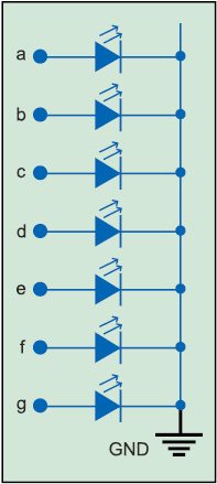
Common cathode display (CCD). In this display, all cathode connections of the LEDs are joined together to a low logic or ground or 0. The individual segment is illuminated by the application of high logic or +Vcc or 1 to the individual anode terminal. The CCD is shown in Fig. 1.
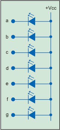
Common anode display (CAD). In a CAD, all anode connections of the LEDs are joined together to a high logic or +Vcc and individual segments are illuminated by connecting individual cathode terminals to low logic or ground. The CAD is shown in Fig. 2.
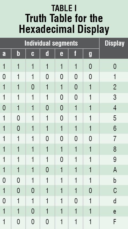
Truth table for display
The segment that should be illuminated is given as 1, which means high, as input. Decimal values from zero to nine are obtained for corresponding binary inputs as shown in Table I. Also, hexadecimal outputs such as A, b, C, d, e and F have been shown. Certain characters appear in lowercase because B looks similar to 8 and D looks similar to 0 on an LED display.

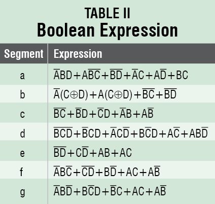
Boolean expression for each segment is shown in Table II.
LabVIEW program
Following are the steps required to design a 7-segment LED hexadecimal display using NI Labview:
1. Open LabVIEW and press ctrl+n followed by ctrl+t to open Front Panel and Block Diagram windows.
2. On Front Panel, from Menu, select View→Control→Modern→ Boolean→Round LED; drag and drop it on Front Panel and label as A (Input A). Similarly, select three more inputs and name these B, C and D, respectively. Arrange these as shown in Fig. 3.
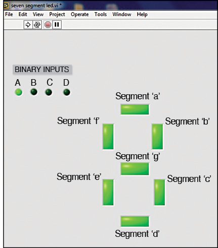
3. Select View→Control→Modern →Boolean→Square LED; drag and drop it on Front Panel and arrange in the form of an actual 7-segment LED display and name each as individual segment a, b, c, d, e, f and g, respectively, as shown in Fig. 3.
4. Go to Block Diagram workspace (Fig. 4). From Menu, select Programming→Boolean→NOT gate; drag and drop it on the workspace for each input as shown in Fig. 4.
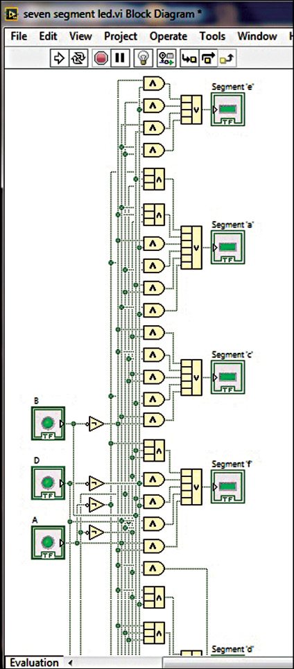
5. From Menu, select Programming→ Numeric→Compound Arithmetic; drag and drop it on the work-space. Right-click on Compound Arithmetic, select Change Mode and choose logic gate (OR or AND) operation, as needed. Compound Arithmetic is used to carry out logical and arithmetic operations for more than two inputs.
6. Similarly, select suitable logic gates for the corresponding Boolean expression for each segment as given in Table II.
Download source code: click here
7. Connect each output of the Boolean expression to each of the indicator (segment) as shown in Fig. 4.
8. Return to Front Panel. Save VI and press Run Continuously to check the operation of 7-segment display giving different binary inputs and also check outputs from 0 to f.
Checking the output
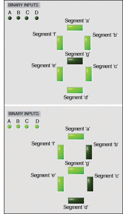
Fig. 5 shows the result of a 7-segment LED (decimal and hexadecimal) display for 0 and F.
