
For example, if a 0.22µF capacitor is used, it gives about 14.4-ohm reactance at 50Hz, 230V.
Suppose the current passing through the capacitor is ‘I’ and mains voltage is 230 volts, then current I through the capacitor is V/X. That is, 230V/14.4 = 15.9 mA.
Thus a 0.22µF capacitor can give only 15mA current for the circuit. So it is important to fix the current requirement of the circuit before selecting the dropping capacitor.
Capacitive power supply
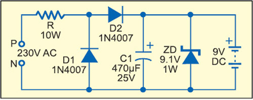
The simplest form of a capacitive type power supply uses an ‘X’ rated capacitor along with rectifier and smoothing components (Fig. 2).

 Here the voltage through the load remains constant as long as the output current is less or equal to the input current. This current is limited by resistor R1 and capacitor C1. R1 is necessary to limit the inrush current at power-’on.’ The high-voltage capacitor C1 acts as a current and voltage limiter which drops 230V AC to a low-voltage AC.
When current flows through D2, capacitor C2 charges to its full voltage capacity and 9.1 volts appears across zener diode ZD. The maximum DC current available from the power supply depends on the value of C1. A low-value capacitor gives lesser current and a high-value capacitor gives more current. Maximum output current (IMax) available from the circuit is:
IMax = 2 π × 50C × 230
where ‘C’ is the value of the dropping capacitor in µF and 50 is the mains frequency at 230V AC. The current available from the circuit shown in Fig. 2 is around 35 milliamps.

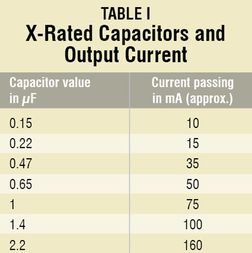
To get the desired output current, it is important to fix the value of the dropping capacitor. The easiest method is to divide the required current by 75, i.e., output current (mA)/75. So the value of the capacitor in µF can be obtained. Table I shows some common ‘X’ rated AC capacitors and the current available from them.
The actual value of current given in Table I will not be available at the output since it may vary slightly depending on the input voltage and current. Voltage drop in the mains severely affects the output current in a transformerless power supply. The components of the power supply will also consume some current. It is better to use a high-value capacitor like 2.2µF if the load requires more than 50mA current.


This article is an example of what we get when a professor of zoology tries to write articles on Electronics!
Lot of nonsense has been written in this article to confuse hobbyists and students.
For example, 230V/14.4 = 15.9 mA? It is simple Ohms Law, and the answer is not mA but AMPERES, yes, the answer should be 15.9 AMPERES! Mr Mohan Kumar, just try to connect a 14.4 ohm resistor across the 230V mains and you shall get your answer….It seems that the author has never actually done any practical projects in electricity or electronics himself.
You are right. Teoretical is one thing and practical work is the other. The difference between these two is big.
And mentioning theoretical work earlier, in this article the author doesn’t seem to work a lot on theoretical knowledge either 😀
Chinmoy Mitra what you have told is wrong. Mohan kumar is right since the reactance of capacitor for 0.22uF capacitor is 14.4 K ohm and thus the 230/14.4*10000=15.9mA.
It’s because the capacitor’s value is incorrect. It is supposed to be 225K value (22uF), which will then give you the rest of these values. 0.22uF or 220nF will give you 14.4K Ohm.
Hi 225K is 2.2uf not 22uf…
YES SIR,
2.2uf
you are correct.
He may have missed to write 14.4KOhm, just a typing error. But don’t say this way. He has described very well.
Hello sir, I need help about smps circuit it is ac 175 to 230v input and output 24v 2.5amp. Dc so pls give m circuit design. In my mail id. Thank u.
DON’T EVER TRY OUT ANY CIRCUIT by the so called Dr.Mohan Kumar!
Ref: http://www.talkingelectronics.com/projects/SpotMistakes/SpotMistakesP14.html
QUOTE “Professor D.Mohankumar must be the WORST electronics engineer I have ever come across. Here is another of his untested circuits:” Unquote.
Dr.Kumar, plse stop…. U are a source of EMBARRASSMENT to YOUR COUNTRY.
WHAT IS THE PURPOSE OF 9V DC BATTERY in FIG 3?
It ia not thw battery it is the 9V output in the DC form
I like your resanble theroy or cktdiagrm
Hello sir,
I had tried this circuit. I had got perfect output from this circuit. But I had found some problems in this circuit. When the 230v ac is connected to this circuit both the zener diodes got heated in this case. I need solution for this issue. Plz tell me sir..
Mobile charger with all protection like over voltage/under voltage protection over charge cut with indicator with 2AMP cap.5v
Non isolated power supply has risk always follow Isolated .
Can I touch this DC voltage.
You will never know whether neutral or connection is proper or not is the are interchange and you touch the ground of the circuit and same time touching the earth.. It will definitely give you a 240 rms shock.
The author of this article has clearly mentioned that It is dangerous to touch this power supply in page number 5 safety Overall this is a Non isolated power and harm you any time. please refer completely. If it is mandatory to touch better take a insurance and move. (Kidding )
Does this work or not?
If it does work what is the ampage ?
i made this circuit (Fig.9) and used to operate Arduino mini it’s work properly, but R1 resistor is heated too much even I used 3W rather then 1w. please tell me, sir, what is the problem or how can I sort out it?
[email protected]
WhatsApp +91 8155010222
Hi dear Schrödinger
Thank you so much for your very useful and informative essay regarding transformerless Power supplies.
would you please answer my questions 😕
1. Is it possible to increase the power of Zener Diods by simply paralleling them? for instance to get one watt by paralleling two 0.5 watt of them?
2. what about increasing Zener Diods’ voltage? for example: to join two pcs. 9.1 and 3.1 volts in series to get a 12 volts Zener diod?
Thank you again
Bye
Hello sir, I need help about smps circuit it is ac 175 to 230v input and output 12v 3.5amp. Dc so pls give m circuit design. In my mail id
the transformer less power supply is dangerous as precautions given ,why then many circuits with ics today uses this type of power supply ?
Dear Sir,
Thank you so much for your very useful and informative essay regarding transformerless Power supplies espesially design considerations.
would you please advice why series resistors and two zener diodes get heated so much and if it is safe to operate the device with such conditions?