


One of the major challenges during a circuit design is to generate low-voltage DC from AC to power the circuit. There are many methods to convert AC voltage into DC. The most common method is the use of a step-down transformer to reduce 230V AC to a lower value AC. This is then rectified and made ripple-free by using a transformerless power supply.
Even though the transformer-based power supply is efficient in providing sufficient current, it consumes much space and makes the gadget bulky. Cost of the transformer is also high. To power low current demanding logic circuits and microprocessor circuits, transformerless power supply is an ideal solution. These power supplies have distinct advantages and disadvantages. These are cost-effective and consume less space, so the gadget becomes handy. But the low current efficiency makes them non-ideal to satisfy high current requirements of most circuits. Moreover, there is no isolation from the mains.
The two basic types of transformerless power supplies are capacitive and resistive. Capacitive type is more efficient since its heat dissipation and power loss are very low. Resistive type power supply, on the other hand, dissipates more heat, so the power loss is quite high. If a circuit requires very low current of a few milliamperes, transformerless power supply is an ideal solution. Before designing a transformerless power supply, some facts about AC dropping through a capacitor or resistor are to be considered.

Design considerations
If a non-polarised capacitor and a resistor are put in series with the AC power line, constant current can be maintained through the resistor, provided that the reactance of the capacitor is greater than the resistance of the series resistor used.
The current flowing through resistor R depends on the value of capacitor C. That is, a higher-value capacitor delivers more current to the circuit. Current flow through dropping capacitor C depends on its reactance, and the value of the current passing through the capacitor is represented as:

IRMS = VIN /X
where ‘X’ is the reactance of the capacitor and VIN is the line voltage (230V).
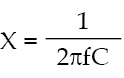
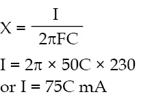
Before selecting the capacitor, it is necessary to understand how a dropping capacitor behaves when it passes current. The capacitor designed to operate in AC voltage belongs to the ‘X’ category with operating voltage ranging from 250 volts to 600 volts. If the mains frequency is 50 Hz, the reactance (X) of the capacitor is:
For example, if a 0.22µF capacitor is used, it gives about 14.4-ohm reactance at 50Hz, 230V.
Suppose the current passing through the capacitor is ‘I’ and mains voltage is 230 volts, then current I through the capacitor is V/X. That is, 230V/14.4 = 15.9 mA.
Thus a 0.22µF capacitor can give only 15mA current for the circuit. So it is important to fix the current requirement of the circuit before selecting the dropping capacitor.
Capacitive power supply
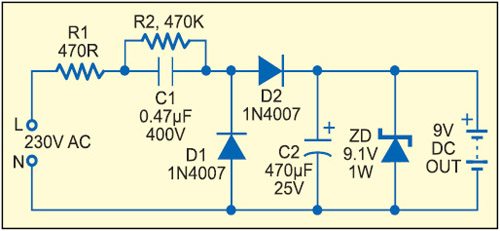
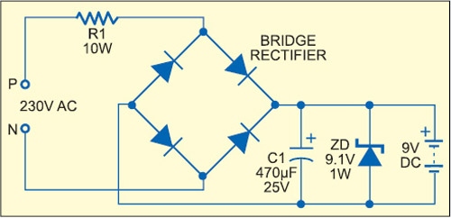
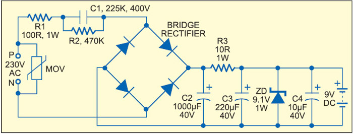
The simplest form of a capacitive type power supply uses an ‘X’ rated capacitor along with rectifier and smoothing components (Fig. 2).
 Here the voltage through the load remains constant as long as the output current is less or equal to the input current. This current is limited by resistor R1 and capacitor C1. R1 is necessary to limit the inrush current at power-’on.’ The high-voltage capacitor C1 acts as a current and voltage limiter which drops 230V AC to a low-voltage AC.
When current flows through D2, capacitor C2 charges to its full voltage capacity and 9.1 volts appears across zener diode ZD. The maximum DC current available from the power supply depends on the value of C1. A low-value capacitor gives lesser current and a high-value capacitor gives more current. Maximum output current (IMax) available from the circuit is:
IMax = 2 π × 50C × 230
where ‘C’ is the value of the dropping capacitor in µF and 50 is the mains frequency at 230V AC. The current available from the circuit shown in Fig. 2 is around 35 milliamps.
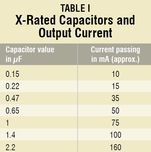
To get the desired output current, it is important to fix the value of the dropping capacitor. The easiest method is to divide the required current by 75, i.e., output current (mA)/75. So the value of the capacitor in µF can be obtained. Table I shows some common ‘X’ rated AC capacitors and the current available from them.
The actual value of current given in Table I will not be available at the output since it may vary slightly depending on the input voltage and current. Voltage drop in the mains severely affects the output current in a transformerless power supply. The components of the power supply will also consume some current. It is better to use a high-value capacitor like 2.2µF if the load requires more than 50mA current.
The relationship between capacitive reactance (X), capacitance (C) and output current (I) is expressed as:
As a safety measure, R2 (470-kilo-ohm) is placed in parallel to C1 as a bleeder resistor. It removes the stored current from C1 when the power supply is disconnected from the mains. This prevents shock hazards, since the capacitor stores more than 400 volts when fully charged. This current may be present in the capacitor for many days even after the circuit is switched off.
Power considerations
Since the circuit is directly connected to high-voltage AC, power rating of the components is important. Capacitor C1 must be X-rated type with a voltage rating of 400 volts or more. The power rating of resistors R1 and R2 must be high enough to handle AC.
Current through R1 is full-wave current, so it is equivalent to the line voltage divided by the impedance of C1. Therefore R1 and R2 must be rated at 1 watt.
Diodes D1 and D2 are rectifiers. Maximum RMS current passes through D1 and D2. So the peak inverse voltage of the diodes must be sufficient to handle this high current. Diode 1N4007 is a good choice as it can handle 1000 volts and 1A current.
Capacitor C2 smooths rectified DC and acts as a buffer to release current to the load. The value of C2 should be double the voltage rating of the zener diode. A 25V electrolytic capacitor will work smoothly.
Zener diode ZD is used to regulate the output to 9.1 volts. It is subjected to most of the current in no-load condition and will get most of the full-wave current once C2 is charged. So the power rating of ZD must be sufficient to handle this high current. Maximum power dissipation that can be allowed in the zener is the zener voltage multiplied by the current flowing through it. If the 9.1V zener passes 35mA current, its power dissipation will be around 318 mV. So a zener rated at 400 milliwatts or more can be safely used.
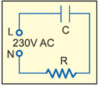
Resistive power supply
In contrast to the capacitive type, a resistive power supply uses the property of resistance to limit the current. As with the capacitive type, the output voltage will remain stable as long as the output current is less or equal to the input current. Resistive power supply is cost-effective and requires less space for its accommodation. But severe power loss through heat is an important drawback. Like capacitive type, it also has no isolation from mains. The output supply is less energy-efficient compared to a capacitive power supply.
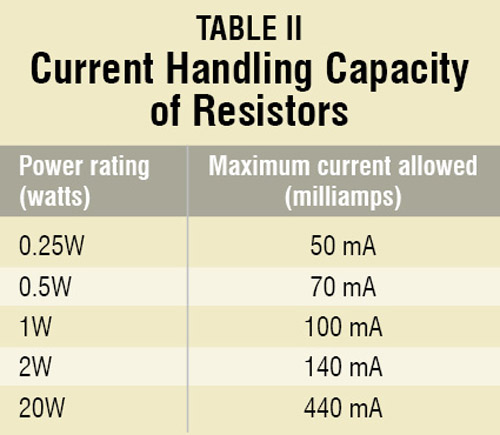
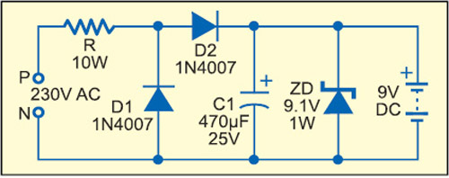
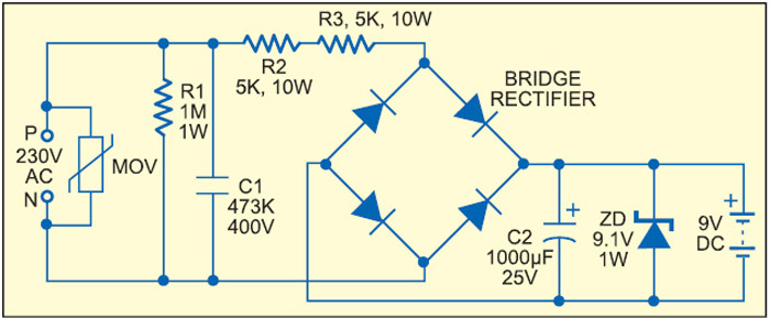
Fig. 3 shows the design of a simple resistive power supply. Before making a resistive power supply, power rating of the components needs critical consideration. All the components should have sufficient current capabilities. Since the resistor is used to drop voltage and current from the mains, power rating of the resistor is important to avoid burnout. Table II shows the current-handling capacity of various types of resistors.
Power considerations
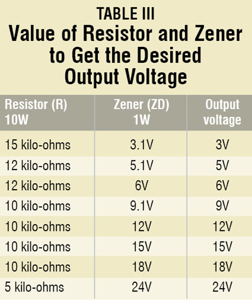
Power rating of the dropping resistor depends on the current flowing through it. Before selecting a resistor, it is important to assess how much current is required for the load. The output voltage also depends on the value of the resistor and the zener diode. Table III helps to select the resistor and zener diode to get the desired output voltage.
A high-wattage type resistor is necessary to reduce the heat generation and power loss. A 10-watt resistor can be used safely without much heat generation. Instead of using a single resistor, it is better to use two resistors in series to get the total value of the resistance required. For example, instead of using a single 10-kilo-ohm resistor, it is better to use two 5-kilo-ohm resistors in series. This will prevent high-voltage transients appearing in the circuit and also lower the potential across the resistor, so the chance of arcing can be reduced.
Power rating of the zener diode is also important as it handles large current in no-load condition. It is better to use a 1W zener diode for regulation. Electrolytic capacitor C1 should be rated twice the value of the zener diode. For fine smoothing, it is better to use a 1000µF, 25V capacitor.
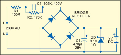
To increase the power supply efficiency, the circuits shown in Figs 4 and 5 can be used.
In both the circuits, current is supplied from the source during both the halves of the AC cycle. So the output voltage remains more stable than with half-wave rectification. Since the output voltage is not referred to phase or neutral, these power supplies cannot be used to control thyristors.
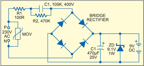
 By adding a few more components, efficiency of the power supply can be further increased. Transient protection is achieved in the capacitive power supply by adding an metal oxide varistor (MOV) across the phase and neutral (Fig. 6).
Resistor R2 acts as a bleeder to discharge C1 at power-’off’ and to filter EMI in the line. The MOV connected across the phase and neutral will suppress transients in the lines.
A resistive power supply using two series resistors instead of one (Fig. 7) reduces high-voltage transients and the potential across the resistors. Capacitor C1 and resistor R1 connected across phase and neutral lines act as filters to prevent EMI flowing into the AC lines. MOV also reduces transients.
Capacitive power supply with more power efficiency
An efficient power supply that can deliver 9V DC at 100 mA is shown in Fig. 8. 230V AC is stepped down to 24V AC by capacitor C1. This low-voltage AC is rectified by a bridge rectifier to give 20V DC. Capacitors C2, C3 and C4 eliminate ripples from the DC and store current to stabilise the output. Resistor R2 attenuates EMI generated in the circuit and capacitor C1 discharges through it when power is switched off. MOV gives transient protection.
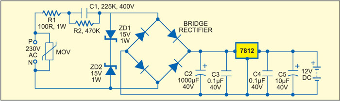
Instead of a zener diode, a series regulator of the 78XX series can be used to give regulated output as in Fig. 9. Zener diodes ZD1 and ZD2 drop 24V AC to 15 volts, which is then rectified and filtered to get ripple-free 15V DC. IC 7812 regulates the output to 12V stabilised DC. The output current will be around 50 milliamperes, which is sufficient to drive most of the light load circuits.
Safety considerations
Capacitive and resistive power supplies are directly powered from 230V AC. So adequate precautionary measures must be taken when building and installing these circuits. An AC-type switch should be placed in series with the phase line to break the power supply. Fixing a fuse will give an additional safety. Power supply section and the electronic circuit must be separated with sufficient spacing while enclosing in the cabinet. Proper shielding and sleeving are required in the AC side of the power supply.
If costly ICs are present in the circuit, do not use a transformerless power supply since these may get damaged in case of a short circuit. Instantaneous power surge in the lines, lightning and short circuits can cause damages in the circuit. Use shockproof cabinets with proper earthing. The circuit can give lethal shock if handled carelessly. So take utmost care during testing and installation. Do not touch any part of the circuit when it is powered.
The author is an associate professor and head of Department of Zoology, Government College for Women, Thiruvananthapuram, Kerala


This article is an example of what we get when a professor of zoology tries to write articles on Electronics!
Lot of nonsense has been written in this article to confuse hobbyists and students.
For example, 230V/14.4 = 15.9 mA? It is simple Ohms Law, and the answer is not mA but AMPERES, yes, the answer should be 15.9 AMPERES! Mr Mohan Kumar, just try to connect a 14.4 ohm resistor across the 230V mains and you shall get your answer….It seems that the author has never actually done any practical projects in electricity or electronics himself.
You are right. Teoretical is one thing and practical work is the other. The difference between these two is big.
And mentioning theoretical work earlier, in this article the author doesn’t seem to work a lot on theoretical knowledge either 😀
Chinmoy Mitra what you have told is wrong. Mohan kumar is right since the reactance of capacitor for 0.22uF capacitor is 14.4 K ohm and thus the 230/14.4*10000=15.9mA.
It’s because the capacitor’s value is incorrect. It is supposed to be 225K value (22uF), which will then give you the rest of these values. 0.22uF or 220nF will give you 14.4K Ohm.
Hi 225K is 2.2uf not 22uf…
YES SIR,
2.2uf
you are correct.
He may have missed to write 14.4KOhm, just a typing error. But don’t say this way. He has described very well.
Hello sir, I need help about smps circuit it is ac 175 to 230v input and output 24v 2.5amp. Dc so pls give m circuit design. In my mail id. Thank u.
DON’T EVER TRY OUT ANY CIRCUIT by the so called Dr.Mohan Kumar!
Ref: http://www.talkingelectronics.com/projects/SpotMistakes/SpotMistakesP14.html
QUOTE “Professor D.Mohankumar must be the WORST electronics engineer I have ever come across. Here is another of his untested circuits:” Unquote.
Dr.Kumar, plse stop…. U are a source of EMBARRASSMENT to YOUR COUNTRY.
WHAT IS THE PURPOSE OF 9V DC BATTERY in FIG 3?
It ia not thw battery it is the 9V output in the DC form
I like your resanble theroy or cktdiagrm
Hello sir,
I had tried this circuit. I had got perfect output from this circuit. But I had found some problems in this circuit. When the 230v ac is connected to this circuit both the zener diodes got heated in this case. I need solution for this issue. Plz tell me sir..
Mobile charger with all protection like over voltage/under voltage protection over charge cut with indicator with 2AMP cap.5v
Non isolated power supply has risk always follow Isolated .
Can I touch this DC voltage.
You will never know whether neutral or connection is proper or not is the are interchange and you touch the ground of the circuit and same time touching the earth.. It will definitely give you a 240 rms shock.
The author of this article has clearly mentioned that It is dangerous to touch this power supply in page number 5 safety Overall this is a Non isolated power and harm you any time. please refer completely. If it is mandatory to touch better take a insurance and move. (Kidding )
Does this work or not?
If it does work what is the ampage ?
i made this circuit (Fig.9) and used to operate Arduino mini it’s work properly, but R1 resistor is heated too much even I used 3W rather then 1w. please tell me, sir, what is the problem or how can I sort out it?
[email protected]
WhatsApp +91 8155010222
Hi dear Schrödinger
Thank you so much for your very useful and informative essay regarding transformerless Power supplies.
would you please answer my questions 😕
1. Is it possible to increase the power of Zener Diods by simply paralleling them? for instance to get one watt by paralleling two 0.5 watt of them?
2. what about increasing Zener Diods’ voltage? for example: to join two pcs. 9.1 and 3.1 volts in series to get a 12 volts Zener diod?
Thank you again
Bye
Hello sir, I need help about smps circuit it is ac 175 to 230v input and output 12v 3.5amp. Dc so pls give m circuit design. In my mail id
the transformer less power supply is dangerous as precautions given ,why then many circuits with ics today uses this type of power supply ?
Dear Sir,
Thank you so much for your very useful and informative essay regarding transformerless Power supplies espesially design considerations.
would you please advice why series resistors and two zener diodes get heated so much and if it is safe to operate the device with such conditions?