
 During sunset or sunrise, the ambient light is not adequate to lead you through the open doorway or make your way around obstructions. To avoid any mishap, here is a twilight blinker lamp that you can place near obstructions.
Twilight blinker lamp circuit
Fig. 1 shows the circuit of the twilight blinker lamp. For powering the circuit, the mains input (230V AC) is down-converted by resistors R1 and R2, capacitor C1 and diodes D1 and D2 into a DC voltage that is low enough to safely charge the back-up battery pack. Resistor R2 across capacitor C1 functions as a bleeder resistor. Zener diode ZD2 protects against over-voltage.
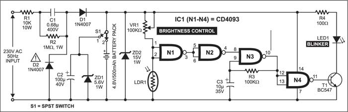
Miniature Ni-Cd battery packs for cordless telephones are easily available at reasonable rates. Use such a battery pack with 4.8V, 500mAh rating for efficient and long-time back-up. The pole of switch S1 should be in position 2 if you use a battery. If you are not interested in the back-up facility, flip switch S1 to position 1.
The rest of the circuit includes a light-detector resistor (LDR1), IC CD4093 (IC1) and a preset (VR1) for brightness control. LDR1 is used as a sensor that has a low resistance during daytime and a high resistance at night.
Circuit operation
When light falls on the LDR, its low resistance provides low level at the inputs of NAND gate N1. The high input from N1 makes the output of N2 low and the relaxation oscillator (built around NAND gates N3 and N4 of IC1, capacitor C3 and resistor R3) does not oscillate. As a result, transistor T1 does not conduct and LED1 does not blink.

On the other hand, in darkness, the high resistance of LDR1 provides a high level at the input pins of NAND gate N1. The low output from N1 makes the output of N2 high and the relaxation oscillator oscillates. As a result, transistor T1 conducts and LED1 blinks.
Transistor T1 is the LED driver. Resistor R4 limits the current flowing through LED1 and hence its brightness. You may connect one or two additional LEDs in series with LED1 to get more light. The low brightness of LED1 will extend the battery back-up time.
Construction & testing
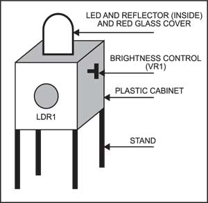
Since the circuit is directly connected to the high-voltage AC supply, enclose it in a plastic case (shown in Fig. 2) to avoid any fatal electric shock. On the front side of the cabinet, leave a hole for LDR1 so that light can easily fall on it. Fix preset VR1 on the other side. You can place the gadget anywhere you want, provided ambient light falls directly on the LDR.

The article was first published in December 2004 and has recently been updated.
