UPSs are great for securing your work and equipment from power line surges and blackouts. They work to provide clean and stable power to electronics equipment such as computers, communications and medical devices. Here are some good reference designs which will let you design a UPS with the right set of parameters according to your requirements – including power environment (single/three-phase), load, availability and battery runtime, etc.
Online UPS with Remote Monitoring and Control For PCs, Communication & Medical Equipment:

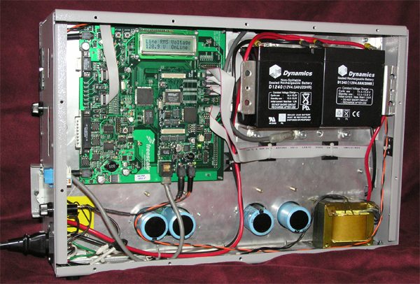
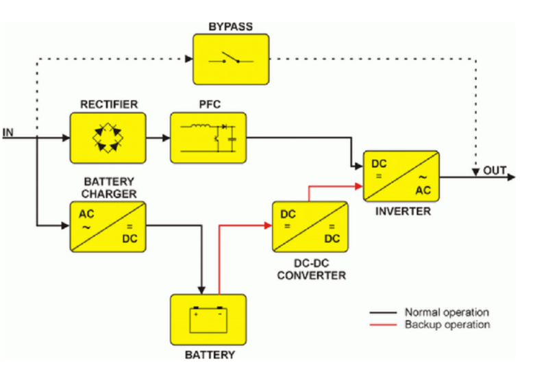
This reference design from NXP provides a low-component count, digitally controlled and cost-effective solution for on-line UPS design. The system hosts 56F8300 family Digital Signal Controller (DSCs) well-suited for UPS design to implement system functions like Power on/off control, DC Bus voltage and AC output voltage regulation, input PFC, battery management, input/output Frequency synchronisation, power source monitoring, etc. The battery charger is a boost/buck DC/DC converter. During normal mode, the DC/DC converter works in buck mode, which steps the DC bus voltage down to the batteries’ acceptable voltage level and charges the batteries. When the battery is fully charged, the converter switches to stand-by mode. If an input power failure occurs, the DC/DC converter works in boost mode, which supplies power to the DC Bus from the batteries. The DC/AC inverter is used to convert the DC voltage to sinusoidal output voltage. The system allows remote control and monitoring via TCP/IP and provides bypass operation during overload or service maintenance. To know more, click here.
450 W Line interactive UPS For PCs:

This is a reference design of a 700VA / 450W UPS implemented using off-line topology. A microcontroller monitors all mains parameters like input/output mains voltage and phase, output inverter voltage, battery voltage, output current and output power in order to ensure the proper level of the output voltage. The UPS involves AVR boost and buck regulation of the mains. The inverter contains the push-pull DC-DC converter and the DC-AC output full bridge generating a quasi-sine waveform. Various communication types like RS-232 joint signal and USB interfaces are supported allowing the UPS to be connected to a PC using an RS-232 or USB cable. The UPS status can be controlled through the ‘UPS Monitor 3.0x’ software that must be installed on the same PC. To know more, click here.
SinglePhase750VAOn-lineUPSForComputers/Servers:

This reference design discusses a 750 VA single phase online uninterruptible power supply (UPS) intended to protect power-sensitive systems like computers and workstations. Its output waveform is a true sine wave with less than 5 per cent THD. The design is based on microcontroller MC9S12E128 and includes a dc/dc step-up converter, a battery charger and an output inverter. The dc/dc converter and the output inverter are fully digitally controlled. The design utilizes indirect PFC control meaning that the voltage (outer) control loop is performed digitally by the microcontroller. The use of the indirect control approach reduces instruction loading of the MCU. The PFC running in average current mode makes the system suitable for medium and higher power applications. Click here to know more about the reference design
1 kVA Offline UPS with Low Switch over Time:
Here is a reference design for a 1kVA Offline UPS using a Switch Mode Power Supply (SMPS) dsPIC Digital Signal Controller (DSC). This UPS works in two modes: Standby mode and UPS mode. Until a failure occurs on the AC line, the system remains in standby mode. In this mode, the system acts as a rectifier charging the battery to its full capacity. A Flyback switched mode charger charges the battery with constant current. In case of power failure, the system switches to UPS mode with the help of a DPDT relay. The push-pull converter steps up the battery voltage to 380 VDC. A full-bridge inverter converts the high DC voltage and filters it with an LC filter to deliver a pure sine wave 220/110 VAC output to the load. This power switchover sequence is made in less than 10ms. Click here to see detailed reference design.
5KVA Single-Phase On-Line UPS Reference Design with XC164CM:
Here is a 5KVA single-phase UPS reference design that offers an integrated UPS solution with 16-bit microcontroller XC164CM. The MCU performs all control functions like charger module control, PWM signals generation, output voltage feedback control, system faults and errors and modules synchronisation. A monitoring board based on Infineon 8-bit microcontrollers XC866 handles LCD and keyboard operations. A full-bridge inverter is utilised whose output voltage is boosted by an isolating transformer and then filtered by the circuit consisting of inductor and capacitors. If case of input mains failure, the battery module is switched to offer power to the inverter to provide uninterrupted power. To know more, click here.


Having a UPS to back your PC up when power is out is a good practice on taking care of your computer but making one yourself might not be as good of a solution as you think it would be due to the limited knowledge such even though design setup is explained well. It is safe to say to buy one instead of building one.
it have a good idea for combine together but i thik difficult to maintenante and make PC heavy weight and hight temp.
well done sir
Soubhik Paul
Could you please provide me UPS System Circuit/idea for IoT device like Arduino Weather Monitor for 24X7 operation atminimum cost? I searched a lot in Internet but every tme I have disappointed.
Oh! I thought that this WERE a DIY UPS Project using PIC Micro! After going thru the manual linked to this article, I found that it is meant for manufacturing process only!!Disappointed very much. “How to Make a Computer UPS!” Please publish a True Sinewave and True DIT Project.