


 This circuit can be used to detect big over-height vehicle moving towards bridges, tunnel entrances and overhead structures, and warn the drivers. It can be developed for monitoring such a vehicle approaching, say, a bridge at night.
The vehicle detection system uses an infrared (IR) sensor to monitor the vehicle. An audio-visual alarm is activated when the over-height vehicle is detected by the system.
For example, a truck loaded with hazardous gases colliding with an overhead bridge can be dangerous. If a vehicle is too high to safely pass under the bridge, a sensor triggers an alarm placed at a distance ahead on the route. The alarm warns the driver to alter the course or stop before colliding with the overhead structure.

Circuit and working
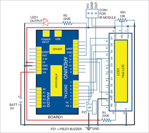
The circuit diagram of the vehicle detection system is shown in Fig. 1. It has an Arduino Uno board, IR proximity sensor module, 16×2 LCD (LCD1), piezo buzzer, preset (10-kilo-ohm), 9V battery and LED (LED1).
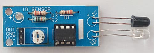
IR proximity module
This module incorporates an IR transmitter and an IR receiver/detector in one package (Fig. 2). It transmits an IR beam continuously. Whenever an object or over-height vehicle is detected, the IR beam reflected from the object/vehicle is detected by the inbuilt IR receiver.

When the reflected IR beam is detected, the vehicle detection system generates an audio-visual alert informing the driver to stop the vehicle, as it may not be safe to continue. LED1 is used as a visual alert whenever an over-height vehicle is detected. Sensing range is adjustable with an inbuilt variable resistor in the IR module.
Arduino Uno
Arduino Uno that has an ATmega328 microcontroller (MCU) is used in the project. It consists of 14 digital input/output (I/O) pins, six analogue inputs, 16MHz crystal oscillator, USB connection, power jack, ICSP header and reset button. Output of the sensor module is analogue. It gets converted to digital through the inbuilt A/D converter of Arduino Uno.
Preset
A 10-kilo-ohm preset (VR1) is a three-legged electronic component used to vary the resistance in a circuit. Here, it is used to control the contrast of the LCD.
LCD
A 16-pin JHD162A LCD module is used in this project as a warning display. It is a two-lines and 16-characters LCD module, which can be replaced with a large LCD display (with some modifications in the circuit) for actual use.
Programming of Arduino Uno is done using Arduino IDE software. The program (vehicle_detection.ino) is written in Arduino programming language.
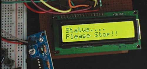
Construction and testing
Make connections as per the circuit diagram. If an object or vehicle is not detected by the sensor, ‘Path is clear’ message is displayed on LCD1. If a vehicle is detected, the message reads as ‘Please Stop!!’ At the same time LED1 glows and the buzzer sounds an alarm (Fig. 3). The circuit can be wired on a breadboard with jumper wires for testing.
Download Source Folder
This vehicle detection system can be implemented using a laser sensor, speaker and bigger display, instead of a proximity sensor, buzzer and 16×2 LCD, respectively. The sensor and display should be installed along the path of the vehicle, before it approaches the bridge, so that the driver gets notified of the warning message well in time.
Navpreet Singh Tung is an assistant professor and project coordinator in the department of electrical engineering at Bhutta Group of College, Punjab

Can I get to know how can we make a working model of this project….like where to attach the lcd screen ….the detector..and Arduino along with the small representation with toy vehicles and an overhead bridge? I need a idea over this ….can you please help.??
The author Navpreet Singh Tung replies:
Sensor system along with arduino must be attached on the roof of vehicle at front side in proper package with opening for sensor on front side to detect any obstacle in front of vehicle at height like bridge,cable etc. LCD must be inside vehicle near driver seat. Appropriate size of wires can be connected with the system. Size of entire project including packging depends on the size of toy. Rest depends on the type and design of toy. Accordingly, system can be adusted.
Thanks for this project. I want to try it but I cant access the source folder you uploaded. can you please forward it to my email, I’ll appreciate. My email is [email protected] Thank you.
Please download source code from here : http://efy.efymag.com/admin/issuepdf/Warning%20system%20for%20overheight%20vehicle.rar
can u please mail me the whole circuit to be incorporated
You can read and print the whole circuit from this page.
Can you please send me a block diagram of this project