

I made my first robot when I was in college and always thought to make totally wireless. So the same I thought about making doors lock operated wirelessly and my shelf lock and a lot of other stuff. Many new electronics engineers this way, either they never get time or they think it’s a lot to learn and create to do something like that. In this article I‘ll focus on how we can actually do this by controlling a servo motor with RF communication. Today we will command and operate a servo motor with RF data link. So for starters we’ll see basic block diagram of how the system flow will work:
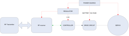
As per figure 1 the logical block of unit has 3 major sections
1. Power : includes power source and regulator
2. Signal processing : includes RF radio , and controller to process received data
3. Drive : includes controller to create drive signal and amplify it to desired power
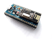
We will be using SmartRF from Knewron Technologies that is an nrf24l01 based device. SmartRF has an 8 bit atmega324 and a RF radio, so our RF receiver and controller is physically same module, but I kept them separate in block diagram for logical understanding.
Servo Operation
Just for a quick brief let’s revise a methodology to drive a servo motor. Out of 3 lines of a servo, two are Power and Ground and third is control line or signal pulse or PWM input, whatever it is called in different parts of engineering world. Most common is a signal line. So we will use this convention for rest of the article. Generally the servos follow same colour convention to maintain standardization.
• RED: Supply Positive
• Black/Brown: Supply Ground
• Orange/White : Signal
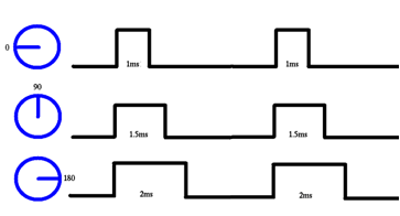
The signal line needs to be fed with pulse of a certain width at a particular duration to keep the servo at a steady position. The width is called as pulse width and duration is related in terms of pulse frequency. You need to check with your servo data sheet for exact values of these two parameters. The frequency is kept constant and the pulse width is varied to get servo to another position.

Part List
• 2 x SmartRF module
• 1 x USB cable
• 1 x Mobile charger with Micro USB header
• 1 x Servo motor
• 3 x Female to Male breakout cables
• 1x Breadboard (optional)
Besides these components, a laptop or PC with serial terminal software will be required to give commands to the setup.
System Setup
Following is the schematic for whole setup and the image for actual setup.

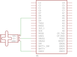
Following are actual setup images.
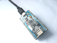
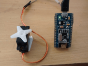
I will be using two identical SmartRF boards for receiver and transmitter. The transmitter is connected to laptop’s USB port and the receiver is powered through a 5V charger.
Control of servo using RF channel
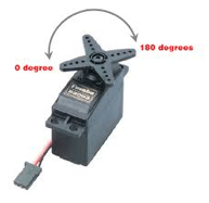
We will be using V3001 bought online for this article, whose pulse width range is
0.9 mS for -90 degrees or 0 degrees
2.1 mS for 90 degrees or 180 degrees
This motor requires a 50 Hz frequency at signal line to operate. The drive software needs to translate the rotation values into pulse width and feed this pulse to servo at pulse rate frequency.
We need to provide the rotation angle to servo through RF link. For this we will broadcast the data on RF channel, from the receiver side, it has to receive the data and convert it into numbers and feed to drive side of software.
As we are using nrf24l01, we’ll be sending commands on SPI and data received will be read over SPI by receiver. There are some available libraries of nrf24l01 or you can build one of your own. So now to keep is simple, we will use sending integer numbers referring to milliseconds. For this demo I’ll keep the resolution low, so we will send integers as follows
90 -> 0.9 mS->-90 degrees
210->2.1 mS-> 90 degrees
The transmitter will send a data from 90 to 210 and receiver will operate accordingly.
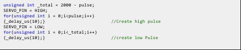
Firstly for receiver I’ll be running a simple while loop to generate pulse and wireless receiver will be put on interrupt. Using a PWM or timer will give you freedom to use controller for other tasks simultaneously. Till the receiver receives a new data it will maintain the last data and position. Following code snippet creates pulses of desired width at 50Hz.
Wireless communication
Nrf24L01 modules are 2.4 GHz transceivers; they can transmit and receive at a max of 2Mbps. The modules have built in settings for setting frequency band, power of transmitter. These modules are code addressable and you can configure their address so that they communicate with only desired modules, this reduces the software complexity and also gives better use of RF channel. These all settings can be done through SPI and configurations can be updated run time, this makes nrf24l01 a very convenient and low cost wireless solution. It does not have a SOC so we need an external controller to command and read from nrf24l01; in SmartRF we have a powerful atmega324a. SmartRF has enough GPIO and processing power that a small application doesn’t even need any other peripheral.
SmartRF has inbuilt USB bridge which makes our setup ever simpler, the transmitter only will be connected to laptop and we can provide data i.e. angle to rotation to it through USART which is connected through the USB bridge, so you can directly communicate with module with your serial terminal software via virtual com port.
For communication we will set the address of receiver and transmitter same, and configure them to run at same frequency channel and data rate. When we send a data from nrf24L01, the hardware takes care about the CRC, preamble and whole communication packet. This data is received by receiver side and decoded to extract only the data packet, once a valid packet is received, IRQ is raised and the controller can read the receiver buffer, all controller has to do now is to read the data and convert it into numbers to be fed to the servo motor.
So over all interface blocks would look like following

If you attempt the setup by yourself, don’t use the USB port to power the motor as it could damage your port, rather use a mobile charger.
Now since we have the setup for receiver and drive circuit, we’ll see the transmitter side. Here we will read serial port to get the angle we desire and transmit it to the receiver. Following code snippet takes angle from serial port and sends it to the RF channel.

Conclusion
The setup is capable of giving commands to servo motors wirelessly; this setup with small RF modules can work up to 15-20 meters in open environment easily. The Module does not require any additional component and this system is very useful to applications where servos are to be remotely controlled. Application including home automation, office automation where servo applications are used for door lock, window pane rail, automatic curtain mover and many similar can be implemented with this setup. With high power RF modules the range can be considerably increased.


Is there any project file with schematic and code to download?