Hardware Components:
You will need the following parts to build this project.
1. Test Board
2. Cable
3. 12V DC
4. Resistor(33ohms)
5. Pot(50k)
6. Low-density lipoprotein
7. BD140npn
8. Bd139npn
9. 5mmLED

Description
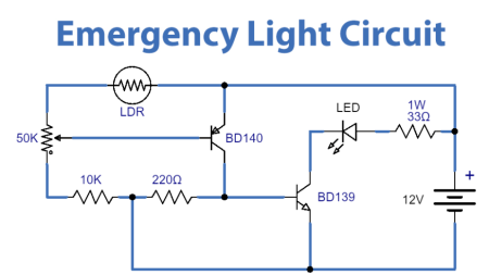
This circuit will turn on a 1 W LED when there is no light on the LDR face. Circuit operation depends on the change of LDR (Light Dependent Resistor) resistance. After completing the circuit, when the LDR is exposed to a sufficient amount of light, its resistance decreases. This then causes the voltage at the base of the PNP transistor to also drop.
When the LDR is exposed to a dark environment, its resistance increases, causing the voltage at the base of the PNP transistor to also increase. This voltage acts as a control signal for the BD139 NPN transistor, which triggers the output LED connected to a 33Ω 1W resistor. The control signal at the bottom of the PNP transistor can be tuned using a 50K potentiometer.
Application
Used as an emergency backup for security systems and industrial sites.
It can be used as an emergency light in both home and office settings.
It can be used in study rooms and workplaces to avoid sudden power outages.
-
This topic was modified 1 year, 8 months ago by
 EFY Bureau.


