

Active star Ethernet (point-to-point). Active star Ethernet (ASE) architecture is a point-to-point architecture in which multiple premises share one feeder fibre through a remote node located between the central office and the served customer’s premises (Fig. 4). Environmentally hardened optical Ethernet electronics—switches or broadband loop carriers—are installed at the remote node to provide fibre access aggregation. The remote node can be shared between four to a thousand homes via dedicated distribution links from the remote node.
Similar to the home-run fibre, subscribers can be located as far away from the remote node as 80km, and each subscriber is provided a dedicated fibre that provides full bidirectional bandwidth. ASE reduces the amount of fibre deployed, lowering costs through the sharing of fibre. ASE also offers the benefits of standard optical Ethernet technology, much simpler network topologies and supports a wide range of CPE solutions. And, most importantly, it provides broad flexibility for future growth.
Passive optical network (point-to-multipoint)
Passive optical network (PON) is essentially a cost-effective optical-fibre-based access system for providing multi-play services (voice, video, data, etc) to both business and residential customers. Passive optical networks use optical fibre and optical power splitters to connect the OLT at the local exchange to the ONU at subscriber’s premises (Fig. 5). No electrical or electronic components are used between these points, all being passive components.

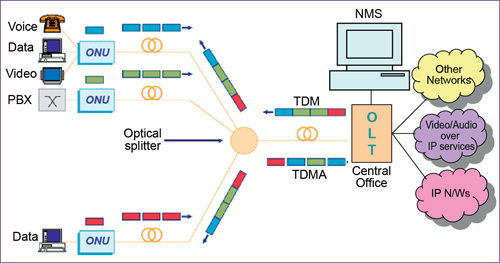
Fig. 5: Passive optical network architecture
This approach greatly simplifies network operation and maintenance, and reduces the cost. PON, being a point-to-multipoint architecture, requires much lesser fibres as compared to point-to-point topologies. The key network elements of a PON system are OLT, ONU, optical splitter and network management system (NMS).
OLT resides in the telecom service provider’s central office and provides traffic aggregation and switching functionality between the core network and PON interfaces. OLT devices support management functions and can manage up to 128 downstream links. In practice, it is common for only 8 to 32 ports to be linked to a single OLT in the central office. Thus, one OLT serves multiple ONUs/ONTs.
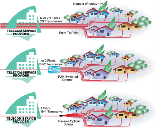
Fig. 6: P2P Ethernet, P2M switched Ethernet and PON
The access node installed within user premises for network termination is termed as ONT. Access node installed at any other location, such as curb/cabinet/building, is known as ONU. ONU/ONT provides access to the users and interfaces to uplink local traffic towards OLT.
Passive optical splitters/combiners provide connectivity between OLT and several ONUs/ONTs. These splitters (distributed or single staged) are available in several options like 1:4, 1:8, 1:16, 1:32 and 1:64.
Network management functions are performed from OLT through the NMS. Time division multiplexed (TDM) data is sent downstream from the OLT towards each ONU where the appropriate portion is extracted for local use. In the upstream direction, a time domain multiple access (TDMA) protocol allocates slots for data transmitted from each ONU to communicate back to the OLT without any contention between different subscribers. Typical distance between OLT and ONU can be up to 35 kms.
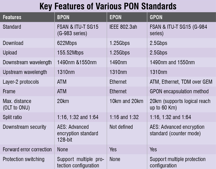
Based on Ethernet technology to create a passive optical infrastructure, PON is classified as Ethernet-PON (EPON) and gigabit Ethernet-PON (GPON). The key features of various PONs are summarised in Table I.
PON requires fewer fibres because subscribers are connected via dedicated distribution fibres to the site, and they share the optical distribution network (ODN) trunk fibre back to the central office. Fig. 6 shows the lesser fibre requirement for PON (EPON and GPON) as compared to the topologies of point-to-point (P2P) and point-to-multipoint (P2M) switched Ethernet.
Point-to-point Ethernet might use either N or 2N fibres, and would have 2N optical transceivers. Point-to-multipoint switched Ethernet uses one or two trunk fibres and thus would save fibres and space in the telecom service provider’s central office (CO). But it would use 2N+2 optical transceivers and would require electrical power in the field.
PON also uses only one trunk fibre and thus minimises fibres and space in the CO, and it also uses only N+1 optical transceivers. Most importantly, it requires no electrical power in the field. The drop throughput can be up to the line rate on the trunk link. EPON can support downstream broadcast such as video. EPON is typically deployed as a tree or tree-and-branch topology, using passive 1:N optical splitters.
Conclusion
FTTx is a family of optical-fibre-based network system that is currently being widely adopted by several telcos to offer cost-effective, lightning high-speed telecom services to its customers through all-optical-fibre network. Technological improvement in the fibre optics domain has led to a new kind of passive optical network elements. EPON and GPON, being passive optical network systems, are very cost-effective for a variety of residential and business services like high-speed Internet, multi-play services, broadcast video, transparent LAN service, and many more. The fibre-optic technology is on the way for a series of technological innovations and developments that will continue to enable vast increases in offered bandwidth over long distances.
The author, currently with Lovely Professional University as assistant professor and previously associated with Bharat Sanchar Nigam Ltd, is PhD in electronics engineering from IIT (BHU), Varanasi and a recipient of senior research fellowship of UGC at Centre of Advanced Study (IT-BHU). His current research interests include wired and wireless technologies for high-speed telecom services


Gentlemen
Can you clarify the contents of OLT the electronic circuit and method of work of the department
Regards