


Table of Contents
Introduction to the Q Factor
The quality factor or ‘Q’ of an inductor or tuned circuit is often used to give an indication of its performance in an RF or other circuit. Values for quality factor are often seen quoted and can be used in defining the performance of an inductor or tuned circuit.
Accordingly this parameter is an important factor in the definition of various RF components and circuits.

Definition and Mathematical Expression of Q Factor
Formal Definition of Q Factor
The Q, quality factor, of a resonant circuit is a measure of the “goodness” or quality of a resonant circuit. A higher value for this figure of merit corresponds to a more narrow bandwidth, which is desirable in many applications.
The Formula for Q: Reactive Power vs. Average Power
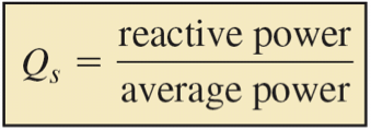
More formally, Q is the ratio of reactive power to average power in the circuit reactance and resistance, respectively:
OR
Q = Pstored/Pdissipated = I2X/I2R
Q = X/R
where:
X = Capacitive or Inductive reactance at resonance
R = Series resistance.
This formula is applicable to series resonant circuits, and also parallel resonant circuits if the resistance is in series with the inductor. This is the case in practical applications, as we are mostly concerned with the resistance of the inductor limiting the Q. A practical application of “Q” is that voltage across L or C in a series resonant circuit is Q times total applied voltage. In a parallel resonant circuit, current through L or C is Q times the total applied current.
Understanding the Q Factor in Resonant Circuit
The Q factor is a dimensionless parameter that indicates the energy losses within a resonant element which could be anything from a mechanical pendulum, an element in a mechanical structure, or within electronic circuit such as a resonant circuit. In particular Q is often used in association with an inductor.
While the Q factor of an element relates the losses, this links directly in to the bandwidth of the resonator with respect to its center frequency. As such the Q or quality factor is particularly important within RF tuned circuits, filters, etc.
Other Expressions
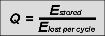
From the definition of quality factor given above, the Q factor can be mathematically expressed as:
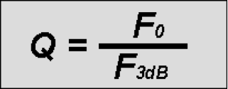
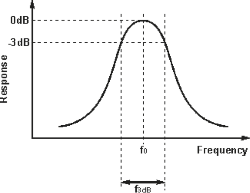
When looking at the bandwidth of an RF resonant circuit this translates to:
Effects of Q Factor
When dealing with RF tuned circuits, there are many reasons why Q factor is important. Usually a high level of Q is beneficial, but in some applications a defined level of Q may be what is required.
Some of the considerations associated with Q in RF tuned circuits are summarized below:
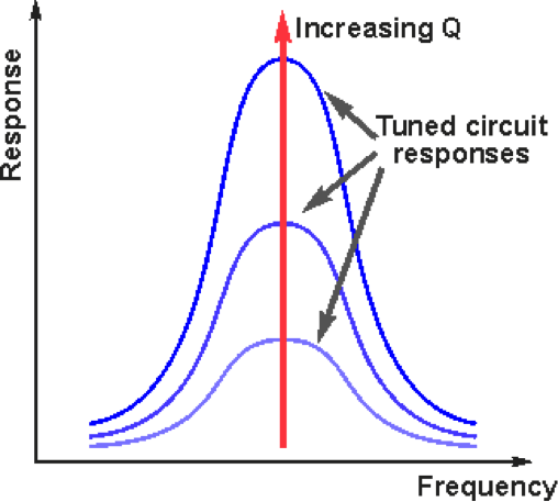
- Bandwidth: With increasing Q or quality factor, so the bandwidth of the tuned circuit filter is reduced. As losses decrease so the tuned circuit becomes sharper as energy is stored better in the circuit. It can be seen that as the Q increases, so the 3 dB bandwidth decreases and the overall response of the tuned circuit increases.
- Ringing: As the Q of a resonant circuit increases so the losses decrease. This means that any oscillation set up within the circuit will take longer to die away. In other words the circuit will tend to “ring” more. This is actually ideal for use within an oscillator circuit because it is easier to set up and maintain an oscillation as less energy is lost in the tuned circuit.
- Oscillator phase noise: Any oscillator generates what is known as phase noise. This comprises random shifts in the phase of the signal. This manifests itself as noise that spreads out from the main carrier. As might be expected, this noise is not wanted and therefore needs to be minimized. The oscillator design can be tailored to reduce this in a number of ways, the chief one being by increasing the Q, quality factor of the oscillator tuned circuit.
- General spurious signals: Tuned circuits and filters are often used to remove spurious signals. The sharper the filter and the higher the level of Q, the better the circuit will be able to remove the spurious signals.
- Wide bandwidth: In many RF applications there is a requirement for wide bandwidth operation. Some forms of modulation require a wide bandwidth, and other applications require fixed filters to provide wide band coverage.
Q Factor and Damping Ratio
The damping ratio is a parameter, usually denoted by ζ (zeta), that characterizes the frequency response of a second order ordinary differential equation. It is particularly important in the study of control theory. It is also important in the harmonic oscillator.
The damping ratio provides a mathematical means of expressing the level of damping in a system relative to critical damping. The various expressions for damping ratio is given below:
Damping Factor in an RLC Circuit
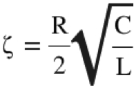
where:
= Damping Factor
R = Resistance (Ω)
C = Capacitance (Fa)
L = Inductance (H)
Q Factor
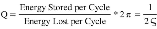
where:
Q = Q Factor
= Damping Ratio
Equation for Damped Harmonic Oscillator
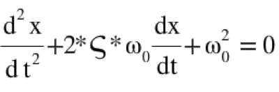
where:
x = Position (m)
t = Time (s)
= Damping Ratio
= Angular Frequency (rad/s)
Damping Ratio
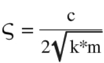
where:
= Damping Ratio
c = Damping Coefficient
k = Spring Constant (N/m)
m = Mass (kg)
Different Damped systems based on Q Factor
- A system with low quality factor (Q < 1⁄2) is said to be overdamped. Such a system doesn’t oscillate at all, but when displaced from its equilibrium steady-state output it returns to it by exponential decay, approaching the steady state value asymptotically.
- A system with high quality factor (Q > 1⁄2) is said to be underdamped. Underdamped systems combine oscillation at a specific frequency with a decay of the amplitude of the signal. Underdamped systems with a low quality factor (a little above Q = 1⁄2) may oscillate only once or a few times before dying out.
- A system with an intermediate quality factor (Q = 1⁄2) is said to be critically damped. Like an overdamped system, the output does not oscillate, and does not overshoot its steady-state output
When choosing defining the Q factor for a system, it is common to opt for the highest level. In this way the optimum performance is normally achieved. However there are instances where lower levels of Q may be advantageous.
I am currently pursuing my final year Btech in ECE at RSET, Cochin

The definitions are incorrectly defined here.
The correct ones are:
Damping factor ( represented by alpha or Xi) = R/2L
Damping ratio ( represented by zeta) = Damping Factor/ Resonant Frequency.
The formula that you have mentioned under Damping Factor is actually for Damping Ratio.
Kindly do the needful.
What are the units of electrical damped oscillator the quality R/2L ?