Continued from Part 2. Here we discuss basics of antenna design.
Antenna design begins by understanding your transmission requirements. You need to know the wavelength / frequency of the signal for the antenna, before beginning work on antenna design. The next step is understanding the antenna type that would suit your application. Moreover certain applications would require several antenna and this may cause a confusion for novices.

A list of currently used antennas
A detailed list of antennas has been mentioned below for your reference. This list is being further updated on a regular basis.
| Monopole Antenna | Helical Antenna | Log-Periodic Dipole |
| Dipole Antenna | Yagi-Uda | Slot Antenna |
| Short-Dipole | Spiral Antenna | Cavity-Backed Slot |
| Half-wave dipole | Corner Reflector | Horn Antenna |
| Broadband Dipole | Parabolic Reflector | Vivaldi Antenna |
| Folded Dipole | Microstrip patch | Slotted Waveguide |
| Loop Antenna | Planar Inverted-F | Inverted-F |
| Cloverleaf Antenna | Bow-Tie | Antenna in wearables |
Parameters in Antenna Design
 All of these and more are being used in some or the other application around us. However designing any of them would involve understanding parameters and suitability for a particular application. Some parameters involved with antenna design besides basic aesthetics are the antenna resonance point or the operating frequency, and the antenna bandwidth or the range of frequencies over which this antenna would be expected to operate.
Any RF antenna consists of capacitive and inductive components in it’s design. Hence this calls for tuning between the two. This brings in a resonance point into the picture. You might be familiar with the relation between capacitance and inductance in tank circuits

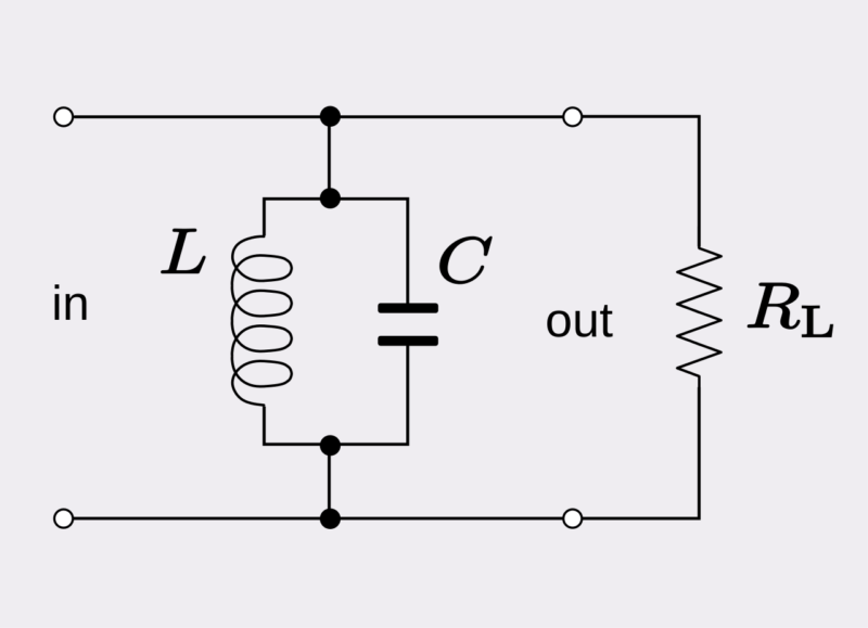
By varying the values of inductance (L) and capacitance (C) in the circuit, we can tune the circuit to receive a particular frequency. This may sound simplistic in reality, However, practical implementation, shows that a circuit tuned at a particular frequency receives a range of frequencies. This brings in another factor the range of operation for the antenna.
Most RF antennas operate upto a certain range of frequencies about the resonant frequency. This becomes a necessity, as the signal transmitted at a particular frequency would undergo several modifications, during its travel. This allows a range of frequencies to pass through, but outside the range the reactance rises to levels that are often too high for satisfactory operation. Other characteristics of the antenna may also suffer due to the increased range of frequencies hence the tank circuit filters the frequencies about the central operating frequency.
Impedance Bandwidth
The impedance of an RF antenna stays same and does not change with its frequency. This causes an increase in the amount of reflected power. In case of a transmitting antenna, beyond a given level of reflected power, damage may occur to either the transmitter or the feeder. This would be a significant factor limiting the operating bandwidth of an antenna but not so much on the reception end.
As far as receiving is concerned the impedance changes of the antenna are not as critical as it will mean that the signal transfer from the antenna itself to the feeder is reduced and will cause the efficiency to fall.
In order to increase the bandwidth of an antenna there are a number of measures that can be taken for eg. using thicker conductors.
Let’s take a look at these types in detail