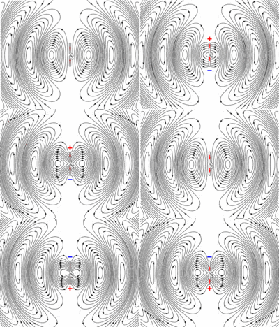
Continued from part 3, here we discuss details about a dipole antenna.
The most commonly used antenna is the dipole antenna used for RF with the most common applications being old tv transmissions. Widely used on its own, it is also incorporated into other RF antenna designs as well, as the driven element. The calculations for an antenna might be complex, a simple dipole antenna however is pretty easy to design. The in-depth analysis to increase the gain and other parameters however are a different struggle.
Dipole antenna basics
The two poles/terminals of the antenna are used as either transmitters or receivers based on the usage. The parameters of the signal cause the signal to be transmitted from the antenna.
At the transmitting end, the signal is fed to the antenna which is split in the middle, to accommodate the feeder. Similarly, at the receiving end, the split is used to take power from the receiver. The length of the antenna is carefully calculated before designing one for your application. It is proportional to the wavelength of your signal in question depending on the type of antenna and application.

The length of most commonly used, half wave dipole antenna is half the wavelength of your signal in question. This resonates with the signal where the electrical length is again half a wavelength long.
As the name suggests, the two parts of the antenna are conductive and can be easily designed from metal wires. These are fed by a signal source for the transmitter or a power source at the reception end. The form of transmission of signal from or to the antenna leaves for a lot of designs. Let’s take a look at some of the variations that might suit your applications.
Types of Dipoles
Some of the variations of the dipole antenna could be
- Half wave dipole antenna: This is the most common type of antenna with length of about half the wavelength of the signal.
- Multiple half waves dipole antenna: Odd multiple of half wavelengths long dipole antenna can also be used if required.
- Folded dipole antenna: While still retaining the length between the ends of half a wavelength, an additional length of conductor connects the two ends together i.e. the antenna is folded back on itself.
- Short dipole: This would be the sortest variant of the dipole antenna. The length if the antenna is much smaller than the half wavelength. However, the feed impedance starts to rise and its response is less dependent upon frequency changes.The reduced length has other advantages.
- Non-resonant dipole: Non-resonance in an antenna helps in operating of the antenna over a very wide bandwidth. It can also be operated away from its resonant frequency and fed with a high impedance feeder.
Dipole antenna current & voltage distribution
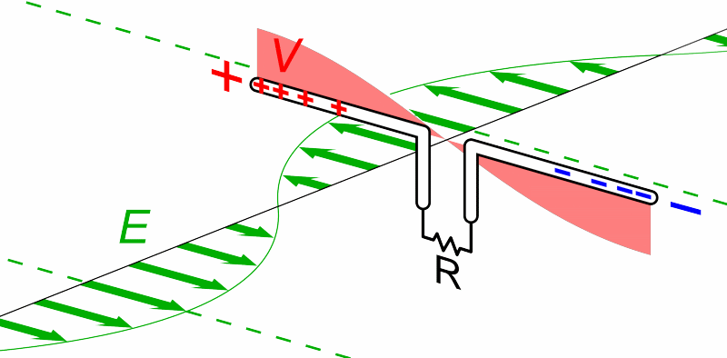
The values of parameters on a radiating element vary on a dipole. The is due to the standing wave phenomenon, which form along the length of the dipole.
Both the current and voltage on the dipole antenna vary in a sinusoidal manner, meaning that there may be other peaks and troughs along the length of the radiating sections dependent upon their length.
For the half wave dipole antenna the current is at a minimum at the ends and maximum in the middle where the feed is applied. The voltage follows a different pattern and is low at the middle and rises to a maximum at the ends. Since it is fed at the center, it provides a low impedance feed point which is convenient to handle. High voltage feed points are far less convenient and more difficult to use. Similar is the case for multiple half wave dipole antenna


So, is there any book for more information?
Hey there Jose,
Hope this helps.
Learn to Design: 5 Free Ebooks on Antenna Design
Good