Noise is generated in all semiconductor devices including triacs. Triacs are used in such power-switching applications as inverter- or motor-control circuits. Triacs and thyristors (silicon-controlled rectifiers, or SCRs) are used in power-switching applications because these can handle high voltages and currents.
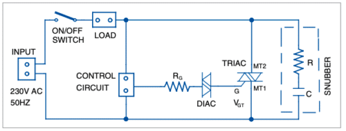
A typical triac application circuit is shown in Fig. 1. Basically, a triac has two thyristors—one conducts during positive half cycle of input voltage and the other during negative half cycle. When the gate terminal is triggered, current can flow either from MT1 to MT2, or from MT2 to MT1.

Trigger voltage (VGT) applied to the gate terminal can either be positive or negative with respect to MT2. But these do not trigger symmetrically, causing differences in positive and negative half cycles of the output. This leads to highlevel harmonics inducing noise and causes electromagnetic interference (EMI) in the circuit.
Triac switching circuits are more prone to noise because when load is turned on, current rises from zero to maximum value suddenly, creating a burst of electric pulses that cause radio frequency interference (RFI). The larger the load current, the worse will be the interference.
In electrically-noisy environments, spurious gate triggering can occur if noise voltage on the gate exceeds VGT and enough gate current flows to initiate regenerative action within the triac.
Harmonics are strong enough to create malfunctions and errors in sensitive electronic devices like computers. The little noise induced in power lines of the PCs may create problems in the most unpredictable ways.
Some ways to minimise noise in a triac circuit are:
- Keep gate connections as short as possible. If these are hard-wired, you can use twisted pair wires or even shielded cables to minimise noise pickup.
- Add a suitable resistor between the gate and MT1 to reduce gate sensitivity.
- Mount the triac leaded package down flat on the PCB or cabinet to stop any vibration-causing noise.
- Place a diac at the gate of triac for cleaner switching.
- Use an RC snubber circuit between MT1 and MT2 to prevent premature triggering caused by voltage spikes in the AC supply or inductive loads such as motors. 6. Use a gate filter to reduce noise coming from AC mains.


