A programmable power supply is a remote-controlled-type power supply that has an analogue input or a digital interface. It is used in a wide variety of applications, including automated equipment testing, crystal growth monitoring, semiconductor fabrication and X-ray generators. It typically employs an integral microcomputer to control and monitor power supply operations. A power supply equipped with a computer interface may use proprietary communication protocols or standard protocols and device control languages such as Standard Commands for Programmable Instruments (SCPI).
Programmable DC power supplies
Power supply manufacturers have to get their devices certified by nationally-recognised primary standards laboratory such as National Institute of Standards and Technology, or simply NIST, or by an internationally-recognised agency such as CSA, UL or VDE.
There are two basic types of programmable DC power supplies that are commonly used: linear and switch-mode.

Linear power supplies operate by rectifying AC line power to create DC and then filtering and regulating it to produce user-selectable voltage or current levels. These are heavier because the 50Hz or 60Hz transformer and associated filters are physically larger.
Switch-mode power supplies start out the same way, rectifying and filtering AC line input voltage; however these chop the DC into AC. These are significantly smaller, lighter and more efficient than linear ones, and have replaced linear supplies in many applications.
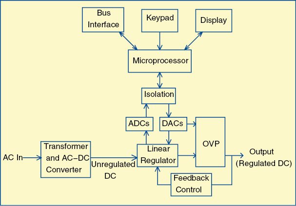
Linear power supplies continue to be a popular choice for test equipment. These are generally durable, accurate and deliver power with little noise. Their simple, direct feedback mechanisms deliver excellent load regulation and overall stability. Fig. 1 shows a simplified block diagram of a programmable linear power supply.
Microprocessors receive input from the user interface or the remote interface. A digital-to-analogue converter (DAC) takes the digital setting and translates it into an analogue value, which is used as reference for the analogue regulator. Setting resolution and accuracy are determined by the quality of this conversion and regulation process. Some common parameters to select a programmable DC power supply are given below:
Resolution and accuracy. Programmable voltage and current settings have resolution and accuracy specifications associated with these. Resolution determines the minimum increment in which the output may be adjusted, and accuracy describes the extent to which the value of the output matches international standards. A DAC with more bits will have more resolution of its output and be able to deliver more distinct values for the control loop to use as reference. Accuracy in a power supply is largely due to error terms in the DAC, including quantisation error.
Read-back accuracy is sometimes called meter accuracy. It determines how close the internally-measured values are to the theoretical values of the output voltage (after setting accuracy is applied).
Read-back resolution is the smallest change in internally-measured output voltage or current that the instrument can discern. It is usually expressed as an absolute value, but may also be given as a percentage of full scale.
Load regulation. It is the measure of the ability of the output voltage or output current to remain constant during changes in the load.
Line regulation. It is a measure of the ability of the power supply to maintain its output voltage or output current while its AC line input voltage and frequency vary over the full allowable range.
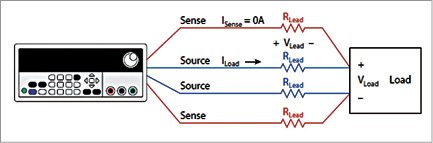
Remote sensing. A programmable power supply is equipped with remote-sensing capability. Remote sensing is required in applications where load is located at some distance, typically more than 3m (10-feet), from the power supply output terminals. You can also use remote sensing if the measured voltage at the load input power terminals is significantly lower than the voltage measured at the power supply output terminals.
Difference in voltage is based on the amount of current and the load lead size and length. It uses a four-wire connection (Fig. 2) so that the voltage you set on the supply is the voltage you get at the device under test (DUT) in spite of voltage drops in cables that carry current between the power supply and DUT.
Analogue interface. DC programmable power supplies typically provide a standard and isolated analogue interface, through which a supply’s DC output voltage, current and over-voltage protection can be set. These values are controlled by supplying a voltage signal, a current signal or by connecting a resistor to the analogue input. For example, you can use the analogue output of a PLC to control the output voltage of a power supply.
Residual AC. Output of these DC power supplies is not perfect DC. Some AC is to be expected on the output. For some applications excessive AC on the output can produce unexpected circuit behavior, so it helps to know the amplitude of the residual AC.
Spurious AC components on the output of a DC supply are called ripple and noise, or periodic and random deviation. These terms are often used interchangeably.
Transient response. Transient response specifications indicate how quickly the output settles to a stable DC value after a change in load or settings. Most power supplies have a significant capacitance in parallel with their outputs to help deliver clean, steady DC. When this capacitance is placed in parallel with load resistance, a time constant results that varies with load impedance. Voltage transient response of programmable power supplies is given for three conditions: increasing load, increasing setting and decreasing setting.
Variable output impedance. These supplies incorporate a variable output resistance feature, which enables test engineers to test the DUT under actual operating conditions. The variable output impedance allows them to simulate the internal impedance of a battery.
Digital interface. In general, output voltage and current of a programmable supply is set most accurately, with the highest resolution, through its digital interface. DC supplies typically offer many different interfaces, including RS232, RS485, USB, GPIB, Modbus-TCP, Modbus-RTU and Ethernet.
In addition to hardware, most DC power supply companies also supply the software you need to easily integrate your DC supply into your system. For example, AMETEK supplies IVI drivers with each supply, and the supplies are programmed using standard SCPI commands. This makes system programming and system integration much simpler.
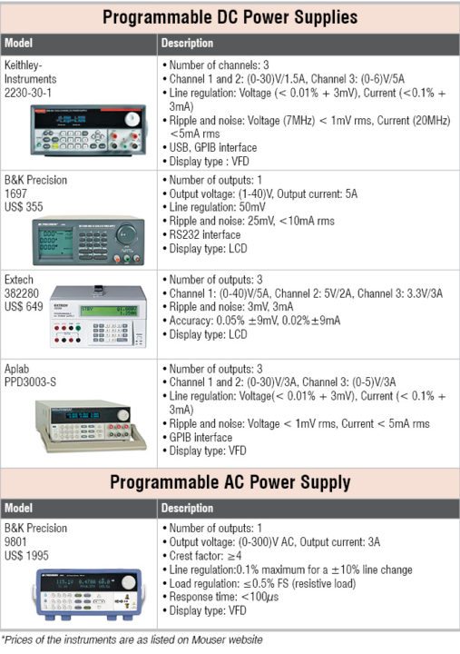
Programmable AC power supplies
Programmable AC sources used in test applications must not only supply a stable source of AC but also simulate power-line disturbances and other non-ideal situations.
Today’s switching AC power sources offer great specifications and powerful waveform-generation capabilities that allow users to generate complex harmonic waveforms, transient waveforms and arbitrary waveforms more easily than ever before. Some can even provide both AC and DC outputs simultaneously and make measurements as well as provide power. This level of flexibility is making it easier to ensure that electronic products will work under adverse conditions.
Some common parameters to select a programmable DC power supply are given below:
Current requirements. To select an AC source you must consider the current your unit under test will draw. Be sure to include inrush and transient currents that may occur during intentional input voltage swings and during different modes of operation.
Worst-case input current. Rectifier-type power supplies and motors have inrush currents anywhere from two to ten times the nominal run current. AC power sources are designed to protect themselves from excessive loads current by either folding back voltage (current limiting) or shutting down output (current-limiting shutdown), and in many cases this is user-selectable.
Crest factor. Crest factor is the ratio of peak current amplitude to rms amplitude of AC. It is important to select an AC source with low impedance and high peak instantaneous current capability. Many AC sources can only support a crest factor of 1.414. With a crest factor rating of up to 3.25:1; AMETEK CSW series AC source, for example, can drive difficult non-linear loads with ease. This translates into driving a rectifier, for instance, that has a 52A peak current at 13A rms at a 120/208 three-phase output.
Power factor. Power factor of an AC electrical power system is defined as the ratio of the real power flowing to the load to the apparent power in the circuit. A load with a low power factor draws more current than a load with a high power factor for the same amount of useful power transferred.
Regulation and distortion. Load and line regulation should be tight and distortion low. Typically, quality AC sources will have a voltage accuracy of ±0.1 per cent and a maximum total harmonic distortion of no more than 0.25 per cent.