This article gives you a comprehensive overview of embedded systems including their characteristics, architecture, development methodology and tools, and testing.
Embedded systems are computer systems designed to perform specific dedicated functions within a larger system. They are embedded as a part of the complete system, hence the name embedded system.
Development of embedded systems began in the 1960s. Apollo guidance computer and the guidance computer of minuteman missile were perhaps the first modern embedded systems. Since the early applications in the 1960s, embedded systems have grown exponentially in terms of power and functionality. Also, the cost of these systems has come down, due to their large-scale proliferation.
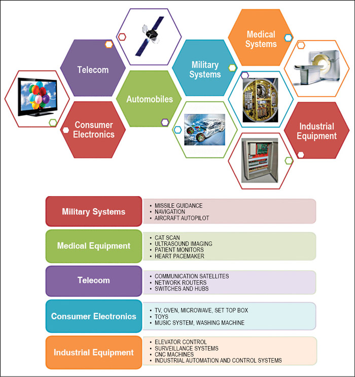
Today, embedded systems span all aspects of modern life ranging from consumer electronics to military systems, medical equipment to telecommunications, industrial equipment to automobiles and so on.
Characteristics of embedded systems
Embedded systems are very different from general-purpose computers. Common characteristics of embedded systems include:
Single function:
An embedded system usually executes only one program repeatedly. In contrast, a desktop system executes a variety of programs. As an example, a washing machine always runs the routine of washing clothes, whereas in a desktop computer you can run a variety of programs like MS Office, games and so on.
Interacts with the real world
Embedded systems are usually connected to real-world devices and interact with them through sensors and actuators.
Tightly constrained
Embedded systems have limited resources available in terms of memory, CPU and peripheral input/output (I/O) devices to complete a given job in the desired time. These systems have power constraints also.
Reactive and real-time
Most embedded systems are required to process the data in real time.
Reliability
Embedded systems need to be highly reliable as the implications of failure are much more severe than of desktop systems.
Others
Embedded systems are mostly not standalone devices and are embedded within a larger system. These are supported by a wide array of processors and processor architectures.
The above-mentioned features play a crucial role during the design, development and testing of embedded systems. They also require a host of diverse skill-sets related to hardware, embedded software, electronics and mechanical domains, which renders further complexity to their development.
Architecture
An embedded system is a combination of computer hardware, software and additional mechanical components designed to perform a dedicated function. The major building blocks of an embedded system include microcontrollers/digital signal processors (DSPs)/field-programmable gate arrays (FPGAs)/system-on-chip (SoC), integrated chips, operating system (including board support package and device drivers), industry-specific protocols and interfaces, and printed circuit board assembly. Usually, an embedded system requires mechanical assembly to accommodate all these components and create the final product or device.
Fig. 1 shows the simplified model of an embedded system. The hardware layer contains all the major physical components and comprises a printed circuit board that accommodates all the semiconductor devices, buses and related electronics. The system and application software layers contain software located on and being processed by the embedded system. Application software layer is the top-most layer comprising the code for a specific application written by developers and utilises services from underlying layers. The system software layer comprises components like device drivers and communication protocols. A special genre of operating systems known as the real-time operating system (RTOS) is usually required to cater to the deadline-driven requirements of an embedded system.
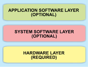
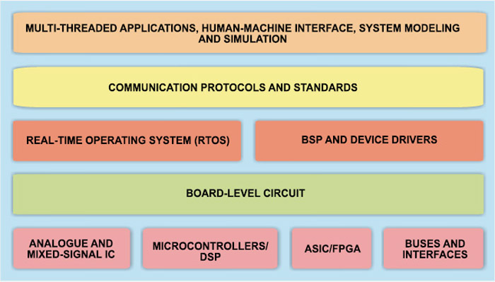
Fig. 2 shows the detailed description of each of the layers discussed above.
Nowadays most embedded designs are configured around 32-bit processors. With the continuing advances in VLSI technology, the trend is towards larger and more powerful processors. The program code and applications running on embedded systems also continue to increase both in complexity and memory requirements. Therefore most of them today have an operating system to manage the hardware and the software resources. ‘C’ family of languages is used for development in majority of embedded systems. Assembly language is still used by many developers, but to write a small portion of their code.
Development of an embedded system therefore requires a host of diverse skill-sets related to hardware, embedded software, electronics and mechanical domains. In a nutshell, with the exponential growth of embedded systems in terms of increased functionality and performance, selection of a particular technology for system development is a tough call for product managers and architects.
Design lifecycle
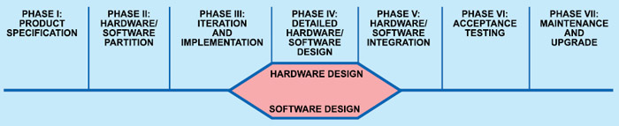
As shown in Fig. 3, the design lifecycle of an embedded system can be divided into following phases: Product specification, partitioning the design into hardware and software components, iteration and refinement of partitioning, independent hardware and software design tasks, integration of hardware and software design tasks, product testing and release, and maintenance and upgrading.
The first step in designing an embedded system is the finalisation of product specifications including functional and non-functional requirements. Functional requirements dictate hardware components including the hardware requirements to process input and output signals, external interfaces and I/O devices. Non-functional requirements include the size, cost and power consumption. The product specifications are finalised through detailed interactions with the customer.
Deciding how to partition the design into the functionality that is represented by the hardware and the software is a key part of creating an embedded system. Hardware/software partitioning is done keeping in mind the different constraints including cost, expertise, market competition and so on. After deliberations of the design team members, the functionalities to be implemented in hardware and software are determined.
After partitioning, hardware and software designs are carried out. The hardware team decides the processor and the other peripheral components to be used depending on the desired functionality, processing speed and memory addressing capability. The software team decides the development platform to be used for software development and carries out the design.
The development platform consists of the hardware board, the operating system, programming language and the development tools. The common programming languages used for development of embedded systems include C/C++, VC++ and Java. The development tools include the editor, compiler, linker, ICE, IDE and so on.
Hardware-software integration is done by combining the hardware prototype, application software, driver code and operating system software. Extensive product testing is done to ensure that it meets all the requirements.
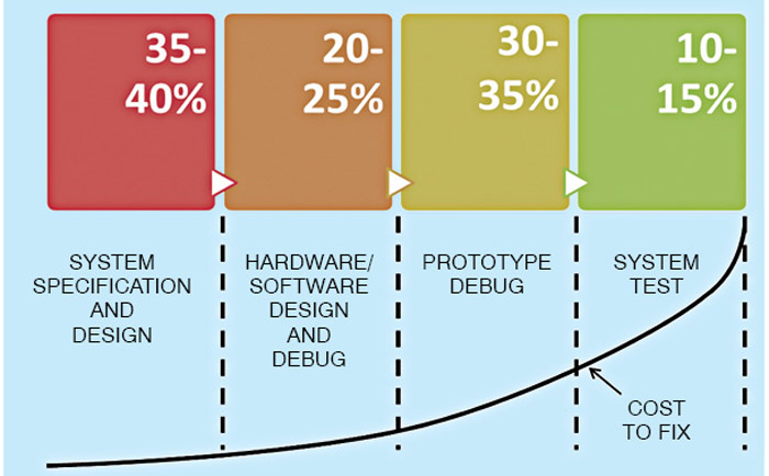
Fig. 4 shows the approximate time spent in each phase of the embedded system design lifecycle along with the cost associated with fixing a defect at each stage of the process. As is evident from the figure, the cost of fixing a defect increases exponentially with time.
Design challenge—optimising design metrics
Embedded system designer constructs an implementation that fulfils the desired functionality, but the challenge is to construct an implementation that simultaneously optimises numerous design metrics. Common relevant design metrics include cost, size, performance, power, flexibility, time-to-market and so on.
Some of the important design metrics are defined below:
Unit cost
It is the monetary cost of manufacturing each copy of the system, excluding NRE cost.
Non-recurrent engineering (NRE) cost
The monetary cost of designing the systems is referred to as the NRE cost. Once the system is designed, any number of units can be manufactured without incurring any additional design cost (hence the term ‘non-recurring’).
Size
The physical space required by the system—often measured in bytes for software, and gates or transistors for hardware.
Performance
Performance is measured by the execution time or throughput of the system.
Power
The amount of power consumed by the system determines the battery life, heat dissipation requirements and system size.
Flexibility
It is the ability to change the functionality of the system without incurring heavy NRE cost. Software is typically considered very flexible.
Time-to-market
The time required to design and manufacture the system to the point that it can be sold to customers. Time-to-market constraint has become very demanding in the last decade or so as the market time windows for products are becoming smaller and smaller.
Time-to-prototype
The time required to build a working version of the system, which may be bigger or more expensive than the final system implementation, but can be used to verify the system’s usefulness and correctness and to refine the system’s functionality.
Correctness
Correctness refers to the confidence that the design team has implemented the system’s functionality correctly.
Safety
The probability that the system will not cause harm.
These metrics compete with one another: improving one often leads to degradation in another. For example, if you reduce an implementation’s size, its performance may suffer. Therefore an embedded system designer should be comfortable with a variety of hardware and software implementation technologies, and be flexible enough to migrate from one technology to another in order to find the best implementation for a given application.
Embedded system design tools
Choosing the embedded system development and debugging tools is as important as the selection of the system resources. Tools required for the development of embedded systems can be classified into three broad categories, namely, toolchain for development of embedded systems, hardware and software debugging tools, and performance measuring tools.
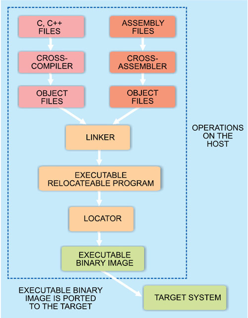
Toolchain for development of embedded systems. The toolchain for building an embedded system (Fig. 5) runs on the host machine and produces code for the target processor. It is basically a collection of translation tools that are pipelined to produce a compatible binary/machine code that can be linked and located into the target processor. It comprises cross-compilers, cross-assemblers, linkers and locators.
Compiler is a program that translates from a high-level programming language (source code) to binary format (object code) that is understandable by the processor. It consists of a pre-processor, an assembler and a linker.
Compilers can be classified as native compilers and cross-compilers. Native compilers compile the source code and create executable code for the same machine, whereas cross-compilers create executable code for a machine other than that on which the source code is running.
Assemblers are computer programs that translate between lower-level representations of computer programs; these convert Assembly-level instructions into binary format (object code). There are two types of assemblers—namely, one-pass assemblers and multi-pass assemblers—based on how many passes through the source are needed to produce the executable program. One-pass assemblers go through the source code once. Any symbol used before it is defined will require ‘errata’ at the end of the object code telling the linker to go back and overwrite a placeholder which had been left where the undefined symbol was used. Multi-pass assemblers create a table with all symbols and their values in the first pass, and then use the table in the later passes to generate code.
Linker is a program that takes one or more object codes generated by a compiler or an assembler and combines them into a single executable relocatable program. Locator performs the conversion from the relocatable program generated by the linker into executable binary image and assigns physical memory addresses to code and data sections within the relocatable program. The binary image generated by the locator is then loaded into the target ROM.
Hardware and software debugging tools
Unlike host-based application developers, embedded system developers seldom develop and test on the same machine. Debugging is done in two phases, namely, the host-based debugging and the target-based debugging.
Host-based debugging is done using an instruction set simulator (ISS). ISS is a program that creates a virtual version of the processor and provides simulated program execution with read and write access to the internal processor registers. ISS comes in different varieties having differing capabilities. Some are limited to simulation of instruction execution only. Most offer breakpoints, which allow fast execution until a specified instruction is executed. Many also offer trace capability, which shows instruction execution history. While instruction simulation is useful for algorithm development, advanced simulators help verify timing and basic peripheral operation, including I/O pins, interrupts, and status and control registers.
Simulators offer lowest-cost development environment. However, many real-time systems are difficult to debug with simulation only. Simulators also typically run at speeds a hundred to thousand times slower than the actual embedded processor, so long timeout delays must be eliminated when simulating.
Target-based debugging is done using tools that mostly reside on the host development platform and debug the code on the target platform. These include debug kernels and remote debuggers, ROM emulators and logic analysers.
Embedded platforms are too resource-limited and specialised to support a full-featured debugger. Therefore debuggers are designed in such a way that major portion of the debugger resides on the host platform (debug kernel) and a small portion resides on the target platform (remote debuggers). The two elements communicate with each other using a communication protocol such as a serial port or Ethernet.
The debuggers perform debugging functions such as setting breakpoints, loading programs from the host, viewing and modifying memory and registers, running from an address and single stepping the processor and so on.
ROM emulators consist of a number of elements including cabling devices to match the mechanical footprint of the target system ROM devices, fast RAM to substitute for the ROM in the target system, local control processor, communication ports to the host and many other features including trace memory and flash programming algorithms. These allow the programmers to quickly download new object code images to run in the target system.
Logic analyser is a tool for examining digital systems. It has two basic modes of operation, namely, the timing mode and the state mode. In the timing mode, an internal high-speed clock determines when the memory of the logic analyser takes a snapshot of the state of the processor or other digital signals in the system. Snapshot is the voltage level or logic level on different pins at a high capture rate so that the timing relationship between various processor bus signals can be monitored. In the state mode, the processor clock is used to capture the state.
Performance measuring tools
These tools include oscilloscopes, chart recorders and so on. Oscilloscopes help to measure the voltage and current signals w.r.t. time. Chart recorders are used to record the signals of interest over a long period of time.
All the functionalities provided by the debugging kernel, ROM emulator and logic analyser are integrated into a single test equipment referred to as the in-circuit emulator (ICE). It emulates (imitates) the processor of the embedded system’s computer and provides a window into the embedded system. The programmer uses the emulator to load programs into the embedded system, run them, step through them slowly, and view and change data used by the system’s software. It offers real-time code execution, full peripheral implementation, and breakpoint capability. High-end emulators also offer real-time trace buffers and time-stamp instruction execution for code profiling.
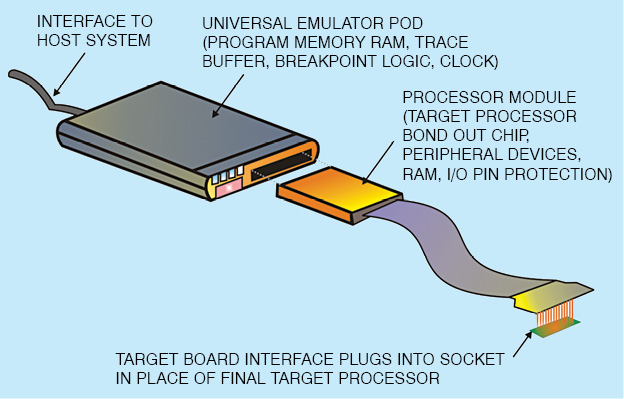
Traditionally, ICE had a plug that inserts into the socket where the processor chip would normally be placed (Fig. 6). Most modern systems use the target system’s processor directly, with special JTAG-based debug access. Emulating the processor, or direct JTAG access to it, lets the ICE do anything that the processor can do, but under the control of a software developer. ICEs attach a computer to the embedded system that provides an interactive user interface for the programmer to investigate and control the embedded system.
The ICE allows the software element to be run and tested on the actual hardware on which it is to run, but still allows the programmer conveniences to help isolate faulty code. It may be mentioned here that the ICE is not emulating hardware. Rather, it is providing direct debug access to the processor. The system under test is in full control, allowing the developer to load, debug and test code directly.
Testing embedded systems
Embedded systems are tested extensively to find bugs in the software, in order to reduce risk, reduce development and maintenance costs, and improve performance. The cost to fix a bug increases exponentially as a function of time in the product lifecycle. Therefore testing should begin as early as possible.
Embedded systems are tested at three levels during the development process—unit level, integration level and system level. In unit testing, individual modules are tested by writing stub code to substitute for the rest of the system hardware and software. The focus is on checking the logical performance of the module.
Integration testing refers to tests that verify the interfaces between different modules or sub-systems. It is done after the unit testing with an aim to expose defects in the interfaces and interaction between integrated components. In a survey it was found out that around 70 per cent of the bugs found during the integration phase of the project were generated by code that was not executed before during unit testing.
System testing is conducted on the complete integrated system to evaluate the performance of the system in accordance with the requirement specifications. It takes at its input the integrated modules and seeks to detect defects both within the inter-assemblages and also within the system as a whole.
Comprehensive testing at each stage is a must for development of any embedded system. Moreover, it is not enough to pass a test once. Every time a program or hardware is modified, it should be retested to ensure that the changes made have not unintentionally resulted in new errors. This testing is referred to as regression testing. Every time a change is made to any part of the code or hardware, it is tested again to ensure its correct functioning.
The approach to testing embedded systems can be classified into two types, namely, functional testing (blackbox testing) and coverage testing (whitebox testing). Blackbox testing assesses the performance of the system vis-a-vis its requirement specifications. In whitebox testing, test cases are used to execute certain portions of the code. Generally, blackbox tests are carried out first followed by whitebox testing. Both types of testing are necessary for rigorously evaluating the system performance.
Blackbox tests evaluate the performance of the system for the desired outputs to a given set of inputs. As they know nothing about how the algorithm is implemented and depend only upon the program requirements and I/O behaviour, they are developed as the requirements are finalised.
Some of the blackbox tests include stress tests, boundary value tests, exception tests, random tests and performance tests. Stress tests intentionally overload the input channels, memory buffers, disk controllers and so on. Boundary value tests employ test cases that check the system performance at transition points in the input and the output value range. Exception tests trigger a failure or an exception mode. Random tests use random test values and are used to evaluate the robustness of the user-interface code. Performance tests do complete performance analysis of the system.
The weakness of blackbox testing is that it rarely exercises all the code. Whitebox testing fills in the gap by ensuring that each code statement, decision point and path is exercised. It is the most important type of testing as it tests each and every part of the code.
Some of the whitebox tests include statement coverage, decision or branch coverage, and condition coverage. Statement coverage tests execute every statement in the code atleast once. Branch coverage tests cause every branch to be executed atleast once. Conditional coverage tests force each condition in a decision to take on all possible values.
Whitebox tests are more expensive than blackbox tests. Moreover, these need to be re-engineered every time the code is changed. Most effective whitebox tests are those that exploit knowledge of the implementation without being intimately tied to the coding details.
Tests that know only a little about the internals are referred to as graybox tests. These tests are most useful when a new functionality is introduced into an already functional code.
The author is a scientist at Laser Science and Technology Center (LASTEC), an R&D establishment under Defence Research and Development Organization (DRDO), India. She has been working on the design and development of a variety of electronics sub-systems for various defence-related applications. She has three books, viz, Satellite Technology: Principles and Applications, Satellite Communications and Electronics Devices and Circuits, to her credit