

Electromagnetic radiation from mobile phone towers is a subject of utmost importance and requires a deep understanding of assessment methods of electromagnetic radiation from these telecommunication installations.
Over the last few years, there have been enormous installations of telecommunication towers around the world. A mobile phone has evolved at a very fast pace from an uncommon, expensive, brick-shaped object used in some western countries to a very convenient and ubiquitous part of human life, with more than five billion subscriptions worldwide. The rapid expansion of this mass telecom technology has been accompanied by some public and media concern about the possible adverse health issues resulting from exposure to electromagnetic (EM) fields, such as those radio frequencies emitted by antennae installed on telecommunication towers.
As the mobilephone base and various wireless technologies such as Global System for Mobile (GSM) communication, Code Division Multiple Access (CDMA), High-Speed Downlink Packet Access (HSDPA), Worldwide Interoperability for Microwave Access (WiMAX), Wireless Broadband (WiBro), Evolution Data Optimized (EV-DO Advanced) and Long Term Evolution (LTE-Advanced) are rapidly expanding and evolving, requirement for mobilephone towers is also growing proportionately. It is therefore high time that a strict regulatory body is put in place to monitor, control and provide suitable directives for mobile tower installations. Otherwise, such mushrooming of telecom towers could create a sense of panic among general public.

There is a perception regarding the existence of a high level of EM radiation in the vicinity of these towers, which may cause adverse biological effects. Numerous studies have considered the evidence and recommended more research on this burning issue. According to World Health Organization (WHO), INTERPHONE (a 13-country coordinated case-control study started in 2000), Independent Expert Group on Mobile Phones (IEGMP) and Scientific Committee on Emerging and Newly Identified Health Risks (SCENIHR) study researches, it has been found that EM radiation can contribute to health deficiency, including increased risk of brain tumours, eye cancers, salivary glands tumours, testicular cancers and leukaemia.
Several surveys have found a variety of self-reported symptoms for people who live close to base stations. Collectively, they have not provided evidence of a relationship, but have had sufficient limitations to leave the question unresolved. International Commission on Non-Ionizing Radiation Protection (ICNIRP) study has concluded that exposure levels due to mobilephone base stations are generally around one-ten-thousandth of the guideline levels. Moreover, WHO has classified mobilephone radiation on International Agency for Research on Cancer (IARC) scale into Group 2B (possibly carcinogenic to humans). This means that there could be some risk of carcinogenicity, so additional research into the long-term, heavy use of mobilephones/wireless technologies needs to be conducted.
There is a need for not only controlling the haphazard installation of towers, but also undertaking systematic study for measurement of the radiation levels in some selected high population density urban areas to ensure that power density levels do not exceed the prescribed threshold limits in the frequency range of interest.
A typical telecom system
A wireless telecom system consists of two major parts: base station and receiver. A base station consists of a telecom tower along with indoor electronics and provides coverage to a very large area. A receiver may be a mobile phone, USB device, separate antenna (indoor or outdoor equipment) or PCMCIA card built in the laptop or computer.
A basic telecommunications base station infrastructure model is shown in Fig. 1. It has several entities such as sectorised antenna system, control and communication electronics, transmitters (Trx cards), media converters (electrical to optical and vice-versa), transmission equipment, power supply module and so on.
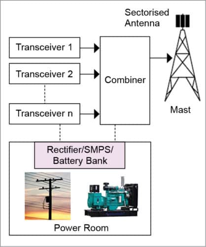
The main function of a base station is to provide air interface to the mobile station, that is, the user carrying the mobilephone fitted with a subscriber identity module (SIM). Other responsibilities handled by the base station include micro-mobility management such as handoff triggering, radio resource management and the like. A base station consists of several radio transmitters whose outputs are combined before being fed to an antenna and finally transmitted as EM waves.
Measurement basics
The real source of EM radiation is the transmitting antenna installed at the telecom site, which determines EM field distribution in the vicinity of a transmitting station.
Where to measure
Field properties of EM fields around the transmitting antenna are related to the field regions of the antenna. Therefore demarcation of an appropriate range of each field region is essential before starting an estimation of the field quantities.
Basically, the space surrounding an antenna is generally sub-divided into four regions: reactive near-field, reactive-radiating near-field, radiating (Fresnel) near-field and radiating far-field (Fig. 2). The reactive near-field region is immediately surrounding the antenna, and its radial distance from the centre of the antenna is 0.62(D3 /λ)1/2. Here, D is the largest dimension of the antenna and is the wavelength (to be valid, D must be large compared to wavelength). In this region, reactive field predominates.
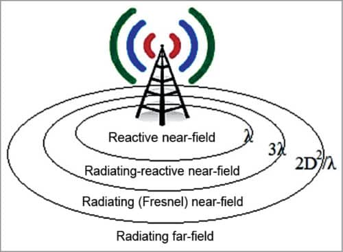
At the boundary of the reactive near-field zone, a transition region exists wherein the radiating field, referred to as reactive-radiating near-field, begins to be important compared to the reactive component. Radial limit of the radiating near-field is 2D2 /λ.
The region between reactive near-field and far-field region, wherein radiation field predominates, is referred to as Fresnel zone. This region exists only if maximum dimension D of the antenna is large as compared to wavelength λ. It is noteworthy to mention that radiation field predominates here, and propagation of EM waves is not a plane wave propagation. Electric (E) and magnetic (H) fields are locally normal, and ratio of E/H ≈ Z0 (intrinsic impedance of free space=377Ω).
Field region beyond radiating near-field (distance≥2D2 /λ or larger value between 3λ and 2D2/λ) is radiating far-field, where field pattern is essentially independent of the distance from the antenna, and radiated power density is constant. In this region, electric (E) and magnetic (H) fields are perpendicular to each other, and the wave propagates as plane wave.
What to measure
What is to be measured {E, H, power density (S) or specific absorption ratio (SAR)} depends on where (reactive or radiating field) the observer is, and on field impedance. Specific absorption ratio is the time derivative of the incremental energy absorbed by (dissipated in) an incremental mass contained in a volume element of a given mass density. It is expressed in units of watts per kilogram (W/kg).
In reactive near-field, it is required to measure both E and H components, or evaluate SAR. Determining SAR instead of field measurement is preferable at the positions located very close to the antenna. In reactive-radiating near-field, if no information on field impedance is available, it is suggested to measure both E and H fields. If information on field impedance is available, it is possible to measure only one field component. If E/H>120π (high-impedance EMF), measurement of E component is required. If E/H<120π (low-impedance EMF), measurement of H component will suffice.
Now, in radiating near-field, it is suggested to measure only E component with impedance taken equal to free space impedance (Z0). In radiating far-field region, measurement of either E or H field component can be done to determine the equivalent power density. However, measurement of E field component is preferred. In far-field region, equivalent power density is obtained from the measured field by calculating, that is, by taking consideration of, Poynting vector.
Some technical considerations
Time averaging. Since mobile communication systems are highly time dependent, it is important to consider time averaging of the concerned fields. In this regard, ICNIRP has mentioned that RMS values of the fields are to be averaged over any six-minute period below 10GHz and over 68/ 1.05-minute period for frequencies exceeding 10GHz (where f is frequency in GHz). In cases of expected time variability of the source, measurements are to be done for an extended period of time. In cases of channel variability, that is, load variability, measurements are to be conducted during time of peak usage.
Multiple sources
In situations where there are multiple sources of radiations, the effect of multiple sources radiating EM waves at different frequencies is considered in a weighted sum. Each individual source is pro-rated according to the limit applicable to its frequency.
In most cases, a typical transmitting station contains many transmitting systems operating on many frequencies. In this scenario, all operating frequencies must be considered in a weighted sum, where each individual source is pre-rated according to the limit applicable to its frequency.
For simultaneous exposure to fields at different frequencies of interest (GSM, CDMA, HSDPA, WiMAX), compliance with the exposure limits is evaluated by considering field strengths due to all the frequencies of interest.
Spatial averaging
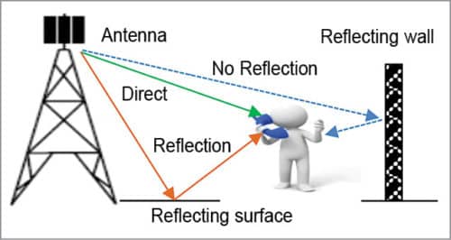
Strength of EM fields of an antenna is highly dependent on the distance/position from the antenna. Near close vicinity of the antenna, these fields are appreciably high. So, spatial averaging is required to get an exact estimation of field strength. Moreover, field strength may also vary with the spatial position due to the effect of reflection, shadowing and scattering about adjacent conducting surfaces. Fig. 3 clarifies such a situation where reflected fields add more values to the fields that may lead to over-estimation of the field during measurements.
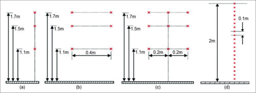
Multi-path reflections can create non-uniform field distribution. Therefore to assess the correct exposure levels, an averaging process is required. Field values should be determined at several points (p) as shown in Fig. 4. Basically, three points are recommended (Fig. 4a), but if higher accuracy is required, the number can be increased to six (Fig. 4b), nine (Fig. 4c), 20 (Fig. 4d) and so on. If there are multiple sources, measurement is performed by dividing the entire area into small grids of about one-square-metre each and taking measurements at individual grid points.
Source power and radiation pattern variability
In telecommunication systems, transmitted power may vary in accordance with the usage of channel (channel allocation) and power requirements in certain atmospheric conditions. Some channels are turned on or off as per need basis in dynamic channel allocation. Variation in channel occupancy (where amount of data transmitted over a channel varies; even if no data is transmitted, channel carrier remains) also alters the amount of transmitted power.
To compensate for adverse propagation conditions, the base station uses automatic power control that results in variation of transmitted power. Sometimes, advanced telecom systems use active antennae that can dynamically change their radiation patterns. These variabilities impose a greater challenge for measurements, since the exact state of the transmitter at the time of measurement may not be known.
Assessment of radiation levels
Assessment of exposure levels can be done either by measurement, by numerical calculations or by EM software simulations. All these methods have almost similar levels of uncertainty and accuracy depending on the method, equipment or software used.
Assessment by measurement
Broadband measurement
An isotropic field probe may be used for broadband measurement of electric field intensity (V/m) or power density (watt/sqm). For a normally compliant radio-communication site, overall measured value of E field or power density with broadband measurement should be within 10 per cent of the reference levels prescribed by ICNIRP for occupational/general public. With broadband measurement, the overall picture of radiation is obtained, but it is hard to get information about contributions to overall radiation level made by individual sources such as GSM, UMTS, CDMA, WiMAX or any other radio-communication system (AM/FM/TV).
A typical test setup for E field measurement is shown in Fig. 5. Some broadband antennae like bi-conical, log-periodic or ridge-guide may be used for measurement in the desired radio-communication frequency band (GSM 900/1800, HSDPA, WiMAX, etc). In such type of antennae, it is required to align the antenna in the plane of incident E field and, thus, the knowledge of polarisation of the radiation source is required.
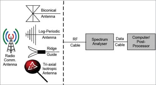
Another type of antenna/probe that is increasingly being favoured for use with the spectrum analyser is the tri-axial isotropic antenna/probe. This is made by three independent broadband sensing elements placed orthogonally to each other. It simplifies the measurement procedure that ideally determines RMS field strength independent of direction and polarisation of the radiation source, since it affords measurement of E field components along all three axes (X, Y and Z).
Measured value of Ex, Ey and Ez, the electrical field strengths corresponding to each axis of the tri-axial isotropic probe, are first corrected for their antennae factors (for each axis) as:
E=AF×V
where E is the electric field strength in volts/metre, V is voltage received by the spectrum analyser and AF is the antenna factor.
Unit of AF is 1/metre. Antenna factor is antenna specific and normally supplied by the manufacturer. Now, the resultant E field strength is added geometrically (root sum of squares).
Frequency selective measurement
As described above, broadband measurement facilitates measurement of the combined effect of all radiating sources. To measure individual response of each and every radiating source, very high sensitive frequency selective intelligent instruments are required. To measure the effect of any particular radiation source, all channels of the source should be transmitting at full power. For example, in the case of GSM, measurement is to be done when all voice channels are running at full load (all control channels are continuously radiating at full power).
Here, the measuring instrument should be operated in the matching bandwidth range and, thus, E field strength is measured for all broadcast control channels (BCCH).
In similar fashion, field calculations can be done for other services like CDMA and WiMAX. Once all peak E field levels are available for all operators running different services, their ratios are calculated with respect to individual field quantity (ELimit) limits (depending on frequency of operation). For compliance, RMS of these ratios should be less than one.
Measurement facts
Assessment of exposure levels by measurement is advantageous in many ways. In this case, effect of all radiating sources is accessed with real parameters and real environment factors including obstacles, reflection from metallic objects and high-rise buildings. Further, little knowledge of radiating source is required.
On the other side, it is difficult to confirm and check that all sources are radiating at full load. Moreover, there is no antenna/probe covering the whole frequency band. Measurement is not possible for radiating sources that do not exist yet. Effect of the presence of staff and equipment on the field distribution has to be avoided. Some sort of post-processing is required because of different limits for different operating frequencies.
Assessment by software simulation
Since assessment of exposure levels by measurement is not always possible due to one or more reasons, several other methods are used for the assessment, such as, by calculations or by software simulations. Many EM simulation software like CST Microwave Studio, High Frequency Structure Simulator (HFSS), Orthoslice, IE3D, WASP-NET, MicroWave Wizard, FEKO and EM Simulator are commercially available. These are being used for microwave analysis, design and optimisation. These simulation software make use of different numerical methods like finite-difference time-domain (FDTD), method of moments (MOM), multiple-region finite-difference time-domain (MR-FDTD), numeric EM code (NEC) and ray tracing model.
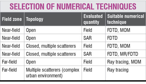
There is no one EM software application or approach that solves all problems equally well. They all have their individual strengths and weaknesses. Selection of the appropriate numerical method depends on the structure to be simulated (antenna, microstrip lines, transmission lines, waveguide structures), availability of computer resources (memory), simulation time constraints, quantity to be observed (SAR/E field/H field/power density), field zone (near/far-field) where exposure assessment is required, topology (open/closed) of the surrounding, accuracy of measurements and so on (given in the table).
FDTD method can be used to predict field values in complex scattering environments by specifying appropriate boundary conditions, or to predict SAR by specifying the dielectric properties and dimensions of the human body and appropriate boundary conditions for closed or open spaces.
For geometries having sparse regions, MR-FDTD is more suitable because the problem space is sub-divided into several independent sub-regions. Fields in the sub-regions are calculated with the use of localised FDTD lattices.
Ray tracing is useful for evaluation of fields in far-field region, especially in large open areas including complex scattering environments. Ray tracing does not enable calculation of SAR. So, a combination of FDTD and ray tracing is used for taking advantages of each of these, that is, calculation of SAR and other field quantities.
MOM method is also an efficient technique to evaluate field quantities in near- and far-field regions (open/closed) emanating from thin-wire conductive structures. But it is not suitable for determining field penetration through dielectric materials. So, MOM is not used for SAR assessment.
Another approach for exposure assessment is synthetic modelling of an antenna system. In such modelling, each antenna is considered to be made of several elementary sources (say, dipole antenna). And each of these is considered as a separate radiating source. But, accuracy is somewhat lower due to negligence of coupling between elementary radiating sources.
For calculations of field quantities, point source model of the antenna system can also be used, but with some limitations. In this model, the radiating source is represented by one-point source situated in the antenna electric centre, having a radiation pattern of the considered radiating source. Boundaries of field regions have to be calculated by taking the actual size of the radiating source. This is because this model does not take into account antenna size. Hence, applicability of this model, especially in near-field calculations, is limited. If the results of calculations are to be accurate, minimum distance between the point of investigation and transmitting antenna has to fulfil requirements for the far-field region (distance =max (3, 2D2/).
Assessment by calculations
Assessment of exposure by EIRP calculations
Calculation of equivalent isotropically radiated power (EIPR) in the direction of maximum antenna gain is an efficient method for the assessment of exposure levels of a base station antenna. EIRP is the product of power supplied to the antenna and maximum antenna gain relative to an isotropic antenna. In this method, site survey is done and several parameters like location parameters, operating parameters and environment parameters are recorded.
Assessment of EIRP and threshold of EIRP (EIRPth) are done at various publicly accessible points (on ground, rooftop, adjacent building, etc) in the environment surrounding the base station antenna.
Threshold value of EIRP should be calculated at the position within the exposure assessment area where power density is maximum. The most important parameter for determining exposure due to elevated antennae (broad coverage antenna—omni directional or sectional) is the vertical (elevation) antenna pattern. Since exposure assessment assumes exposure along the direction of maximum radiation in the horizontal plane, horizontal (azimuth) pattern is not relevant.
For a shared site, EIRP and EIRPth have be to calculated. Cumulative ratio should be less than unity at all points outside the exceedance zone for normally compliant site.
Calculation facts
The beauty of exposure assessment by calculation is to pre-estimate the exposure from non-existent radiation sources. Calculations consider maximum possible radiation (ERP) that leads to maximum possible exposure levels. It is also possible to make calculations in areas with no access. It gives an opportunity to apply mitigation techniques to reduce radiation levels, if required.
Accuracy of results depends on the model used and on the exactness of description of transmitting antennae. Influence of reflections is ignored in the calculations that may degrade the accuracy. For very accurate results, a detailed and precise description of the radiating antenna and the exposure environment is required.
Conclusion
There is a strong perception related to the existence of a high level of EM radiation in the vicinity of telecom towers, which may cause adverse biological effects. So, it is about time an exhaustive assessment of radiation levels and their possible health effects is made, and guidelines for safety are laid down accordingly. If EM radiation levels in any area accessible to humans are higher than the prescribed limits, it is strongly recommended to take necessary action to reduce the radiation levels.
Dr Rajiv Kumar Singh holds a PhD in electronics engineering from IIT (BHU), Varanasi, and is currently employed with Institute of Engineering & Technology, Lucknow as assistant professor. He has received senior research fellowship of UGC at Centre of Advanced Study at IIT, Varanasi. His interests include wired and wireless technologies for high-speed Internet access


The article is very informative.
please send me such articles about INDIAN TELCOM TOWERS,