

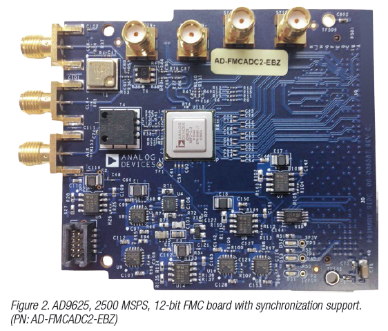
Historically, increasing the instantaneous bandwidth while maintaining the required linearity required using either multiple overlapping receivers or an interleaved architecture. The overlapped receivers each digitise a portion of the required bandwidth with digital signal processing used to recombine the data and observable spectrum from each channel. For interleaved architecture, it is often used with calibration required to minimise the phases, offset, and gain differences between the converters. Both options are generally expensive to implement but the digital signal processing is often customised to the implementation. RF sampling ADCs such as the AD9625 offer solutions to the next generation of systems providing greater instantaneous bandwidth but with higher linearity to maintain the sensitivity levels required. Such ADCs also support synchronising of multiple converters, often required for angle of arrival determination, and has integrated digital down-converters (DDC) to decimate and observe a smaller portion of the frequency spectrum on the output. Devices that support parallel and serial interfaces (including the JESD204B standard) are important to support the high data rate and low latency requirements in many of the EW systems.

Channeliser Overview
Despite particular signal characteristics in EA, ES, and EP systems, a common component is the digital channelised receiver, or channeliser. The channeliser splits a wide bandwidth into smaller ones to separate signals of interests from noise and interferers so that low signal-to-noise ratio (SNR) and time sensitive signals can be reliably detected in individual subchannels. Most digital channelised receivers consist of a filter bank and fast Fourier transform (FFT).
As a design engineer, one of the challenges here is that every new EW design or upgrade usually requires developing a more complex channeliser. This is because new designs usually bring about necessary upgrades in hardware, providing for higher speed converters and more processing performance essential to keep up with ever changing global threats. To accelerate the development of the channeliser and reduce internal research and development (IRAD)cost, we use a super sample rate FFT IP and FIR filter IP core capable of handling multi-GSPS converter inputs. These IP cores will optimise a solution for you based on a wide set of input parameters, as shown in Figure 3.
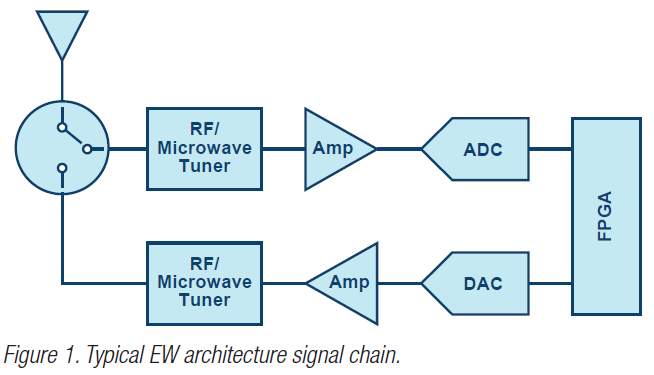
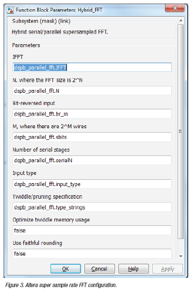 Figure 4 depicts the role of the channeliser in a general EW system block diagram, in which the digitised incoming radio frequency (RF) wideband signal is down-converted, and digitised before feeding into the channelised receiver. Signal detection and estimation are performed on individual channel outputs to discern threats from neutral and friendly signals. Once threats are identified and data based, cfertain EW systems will counter the threats through jamming. In this process, the receiver may produce various jamming signals. These jamming signals can appear in the forms of notched white noise or regenerated false reflection signals, that is, DRFM, to the hostile transmitter. The jamming signal passes through the inverse channeliser, whose role is to reconstruct a wideband reflection signal. The reflection signal is emitted after up-conversion back to the hostile transmitter.


