


Using this 30 minute timer circuit you can switch on an appliance for a desired time. The circuit provides selectable time settings of 1, 2, 5, 10, 15 and 30 minutes, and can be used for domestic as well as industrial applications.
30 minute timer circuit
The circuit can be divided into two sections—power supply and timer. The power supply is built around transformer X1, bridge rectifier BR1, capacitor C1 and 12V voltage regulator IC LM7812 (IC1). The 230V AC mains supply is stepped down by transformer X1 to deliver the secondary output of 12V, 250 mA. The transformer output is rectified by full-wave bridge rectifier BR1, filtered by capacitor C1 and regulated by IC1. The circuit can also be powered by a 12V battery. The power source can be selected by using switch S2.
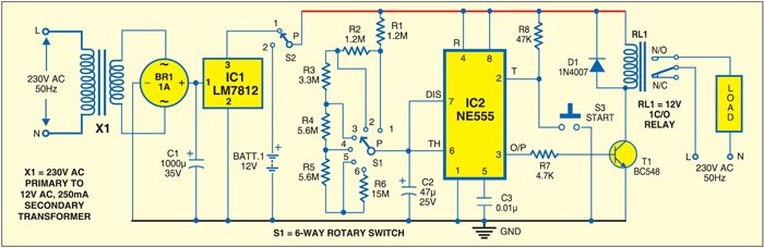
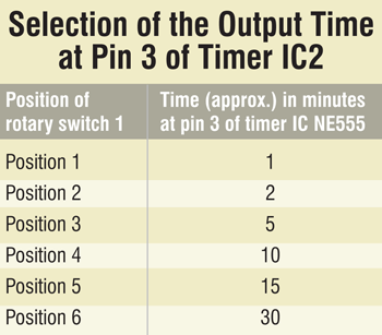
The timer section is built around IC NE555 (IC2) along with resistors R1 through R6, capacitor C2, transistor BC548 (T1) and a 12V relay. IC2 is configured in monostable mode to provide the different time settings ranging from 1 to 30 minutes. The desired time is selected by rotary switch S1 as shown in the table. Pressing switch S3 starts the operation. Once triggered, the timer returns to its original state after the preset time.

Circuit operation
Capacitor C2 charges through a resistor or combination of resistors R1 through R6. When start switch S3 is pressed, the monostable triggers and its output pin 3 goes high for the time selected by the position of rotary switch S1. The output time (T) of the monostable in seconds is T =1.1RC.
Construction & testing
Assemble the circuit on a general purpose PCB and enclose in a suitable case. Fix the unit near the appliance that has to be controlled. Use a 12V relay (RL1) with contact current rating suited for the the appliance.
The article was first published in January 2012 and has recently been updated.

Sir I want to Make a ckt for water level controller without microcontroller.
I want low mid high level +dry run sensing +555 ic for turning off motor in a given time if there is no water at inlet valve.
Please help me out
Anyone with an idea on how I can regulate the speed of an hausklin hematocrit centrifuge, to achieve 1000rpm up to 12000rpm, @ specified time range from 1minute to 30minute. Thanks
Hello, I would like to do that circuit on a solderless breadboard. Can you show me how, please? I’m referring to the 30min timer diagram. Thanks