


 This is a simple audio-frequency (AF) amplifier using the popular audio amplifier IC TDA2003. The IC comes in a 5-pin TO-220B package.
Audio amplifier circuit and working
Fig. 1 shows the circuit diagram of the 3W/6W AF amplifier built around IC TDA2003 (IC1), an 8-ohm, 6-watt speaker (LS1) and a few other components.
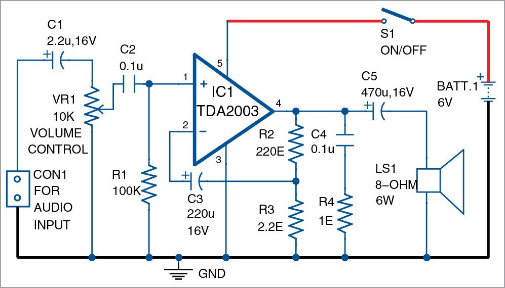
The amplifier IC delivers 3W output power using a 6V, 500mA power supply, and 6W output power using a 12V, 500mA power supply, with an 8-ohm, 6-watt speaker.

Pin 1 of TDA2003 is the input terminal, which is connected to ground through a 100-kilo-ohm resistor. The audio frequency (or audio signal) is fed to pin 1 of IC1 through the combination of a 10-kilo-ohm potmeter (VR1) and capacitors C1 and C2. Potmeter VR1 is used as volume control. Pin 3 of IC1 is connected to ground. Pin 4 is the output terminal, which is connected to one terminal of the speaker through a 470µF, 16V capacitor (C5). It is also connected to ground through a 0.1µF capacitor (C4) and a 1-ohm resistor (R4).
Pin 5 of IC1 is connected to +6V power supply via switch S1. Power supply can be provided through a 6V battery or a 6V DC adaptor. Use of a suitable heatsink is recommended for IC1.
Construction and testing
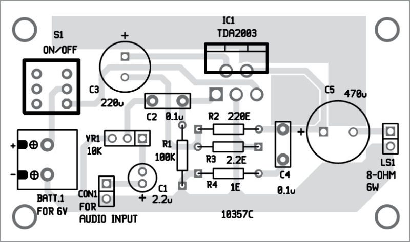
An actual-size, single-side PCB for 3W/6W audio amplifier using TDA2003 is shown in Fig. 2 and its components layout in Fig. 3. After assembling the circuit on the PCB, enclose it in a suitable box.

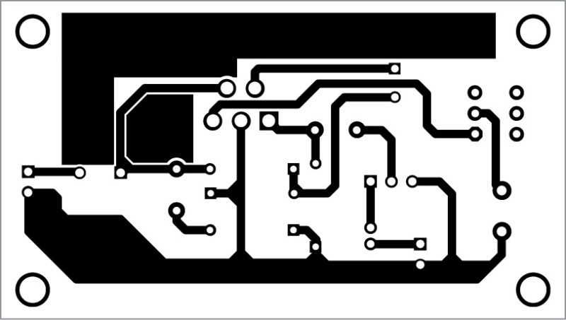
Solder TDA2003 and other components using a 25W soldering iron. Use a 2-pin connector for input and output connectors, to make your prototype safe and clean.
For testing the circuit, connect a 6V battery to the circuit. Also, connect an 8-ohm, 6-watt speaker to LS1.
Download PCB and Component Layout PDFs: click here
If a 12V DC supply is used, voltage ratings of C1, C3 and C5 should be 25V or above.
Take a metal screwdriver and gently touch at input pin 1 of IC1. If your circuit is wired properly, you will hear a humming sound from the speaker. Else, vary potmeter VR1 to increase the volume until humming sound is heard from the speaker. Now your circuit is ready to use.


Can the same circuit be applied for TDA2030 IC??? And if some changes required please mention. Thanks in advance.
@Sayantan
No,the TDA2030 is a class AB amplifier which uses a different circuit- and in most cases split supply with V+/V-/GND
so you can’t use the same board design
@Nobody
Can Tda2030A give full output with a Single power supply instead of Split supply (V+ V- Gnd) by any means ?
what if i want to add the gain and bass potentiometer. how do i connect them? thank you in advance
What’s the use of changing the capacitor C3 by 220 uF instead of 470 uF as in datasheet and C5 by 470 uF instead of 1000 uF ?
2. And what’s the function of Supply Voltage Rejection ?
Dear Sir,
This circuit is giving only giving 3 Watts @ 12 Volts, 500 mA supply instead of 6 Watts before Clipping.
There is also clipping when volume is increased further (above 3 Watts level)
What’s the function of 100K resistor across pin 1 & ground ?
THANKS…. I made It…. Works…. But want to increase Bass Sound
Are you getting clipping of audio in full volume ?
Why the pcb layout and components overlay is not provided for download ?
The images available here can’t be printed in actual size.
Thank You Anirvan, we have updated the article with PCB and Component layouts.
can you give me a clear outlined principle of operation with the function of each component
Build it and works very well, using 9V-12V / 3A to amplify my guitar preamp. Doesn’t drop in high volume and get some balls from it. Thank you, this circuit so useful and excellent.
Thank you for your valuable feedback.
What’s the function of 100 k resistor (R1) across pin 1 ?
My current project is to convert an old sewing machine case into a powered speaker cabinet. The top will house the speaker(s) with a jack for speaker connection. I have a pair of 6×9’s and tweeters that I have salvaged from an old stereo consul. I am considering the TDA 2003 circuit and have a few questions. I plan to power it with a 6vdc, 500ma adapter and want the option to be able to connect a 5vdc power bank. Will the 2003 operate on 5v dc? (I anticipate a drop in the out put). The speakers are 3 watts 8 ohms. Will the circuit work if I wire them in parallel (4 ohms)? Do you have any other plans that would better suit my project?
The TDA2003 is designed to operate within a voltage range of 8-18V DC, so running it at 5V may result in significantly reduced output or it may not work at all.
Regarding wiring speakers in parallel:
If you wire your 8-ohm speakers in parallel, the resulting load will be 4 ohms. The TDA2003 can handle a 4-ohm load, but you should ensure that the output power does not exceed the speakers’ rated capacity to avoid damaging them.