


 While you can connect your analogue input/output devices to Arduino very easily, it is not so easy with Raspberry Pi (Raspi). There are no analogue GPIO pins on Raspi; all GPIOs of Raspi are digital.
The problem can be solved by adding additional analogue-to-digital converter (ADC) processors on top of Raspi; better still would be adding a small Arduino (say, Arduino nano) on top of Raspi.
However, simple resistive-type analogue-input devices can very easily be connected to Raspi by adding a small resistor-capacitor resonating circuit built around a resistor and then measuring the charging time of the capacitor. Here is a program for measuring the light intensity and then printing it out on the monitor using an LDR and a capacitor.

Interfacing the sensor
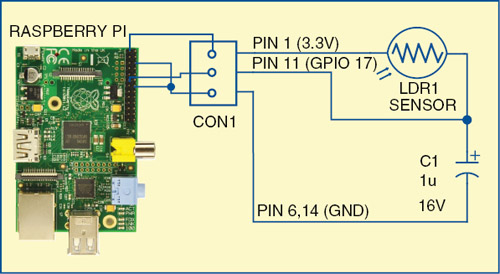
Let us say that our analogue device is a light dependent resistor (LDR) that changes its resistance as per the light intensity. For capacitor, we will use a small one, so that the charging time is precise. Any small 1μF electrolytic capacitor (which has a + lead and a – lead) will work for our purpose. With a bigger capacitor, the charging time increases, so does our measured value number. Moreover, a very big capacitor (100μF or more) may not be fully charged at all from a poor Raspi power.
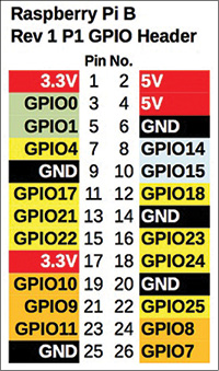
The circuit diagram of an analogue sensor on Raspi is shown Fig. 1. Pin details of the connector on Raspi B board are shown in Fig. 2. for clarity. The capacitor works like a water tank and the LDR acts like a thin pipeline to fill it up.
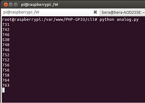
The analog.py program is written in Python script, which enables the Raspi input pin to accept the signal from a sensor like LDR and output signal intensity values on the screen. The program output screen is shown in Fig. 3. The reading variable in the code is nothing but a counter. Counter value is the measurement of LDR input indirectly proportional to light intensity.
Once the capacitor gets fully charged, the attached GPIO pin (GPIO 17) senses a ‘1’ to it and the counter stops. In the code, first we set the GPIO pin as Out and then set it as Low. Then, we set the GPIO pin as In. The LDR slowly charges it to ‘1,’ and the moment the GPIO pin becomes ‘1,’ the process reverses—the reading becomes ‘0’ and the GPIO becomes Low again. We have kept a 0.5-seconds sleep time within which one cycle gets over with a clear margin.
Once that state is achieved, we reset the GPIO pin to Low and the cycle continues. Mostly, within 400ms (milliseconds), the capacitor gets fully charged and in every 0.5 seconds we reset the GPIO pin, so that the counting cycle is well clear off the reset cycle.
analog.py
import RPi.GPIO as GPIO, time, os
GPIO.setmode(GPIO.BCM)
def RCtime (RCpin):
reading = 0
GPIO.setup(RCpin, GPIO.OUT)
GPIO.output(RCpin, GPIO.LOW)
time.sleep(0.5)
GPIO.setup(RCpin, GPIO.IN)
while (GPIO.input(RCpin) == GPIO.LOW):
reading += 1
return reading
while True:
print RCtime(17) # Read RC timing using
GPIO pin #17
Direct a torchlight on the LDR and the value will change according to light intensity. There is no absolute value of measurement as such. The number varies uniformly depending upon the intensity from 75000 (dark) to 50 (direct LED torch light) and you have to make your reading from this range.
Note. The process is not very efficient. In case the Raspi computer is busy or multi-tasking, the results may vary.
Somnath Bera is an avid user of open source software. Professionally, he is a thermal power expert and works as additional general manager at NTPC Ltd
