


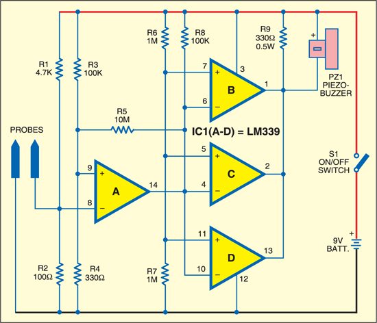
Here is a pretty simple, low-cost audible continuity tester that makes use of just one quad comparator IC LM339, some resistors and a piezobuzzer. The circuit including the comparator works off a single 9V battery. Only one of the quad comparators is used in its real role, while the remaining three comparators, connected in parallel, are used for directly driving a medium power piezobuzzer.
Audible Continuity Tester Circuit
Voltage divider made of resistors R1 and R2 sets inverting pin 8 of comparator ‘A’ at around 190mV level, while resistor pair of R3-R4 maintains non-inverting pin 9 of same comparator ‘A’ at a fixed level of around 30 mV. Resistor R5 connected between the output and the non-inverting input provides the necessary feedback.
An effective solution is to use positive feedback to introduce a small amount of hysteresis. This has the effect of separating the up-going and down-going switching points so that once a transition has started, the input must undergo a significant reversal before the reverse transition can occur.

Circuit operation
In its quiescent state, the output is at low level since its inverting pin is at a higher positive potential (190 mV) than the potential at its non-inverting pin (30 mV). The low level at inverting terminals of ‘B,’ ‘C’ and ‘D’ comparators (connected in parallel) switches their outputs to high state (closer to the supply voltage). Thus both input terminals of the buzzer are nearly at the same potential and hence it does not sound.
Only when a resistance of less than about 15 ohms is connected between the probe tips, will the inverting terminal of comparator ‘A’ fall below 30 mV, resulting in reversal of the polarity at output pin 14 of comparator ‘A.’ This will, in turn, cause the combined output of comparators ‘B,’ ‘C’ and ‘D’ to go low and thus cause the buzzer to sound. The output node of the three comparators can sink more than 50 mA of current to directly drive a medium-power buzzer.

The circuit given here will recognise a resistance of less than 15 ohms for sounding the buzzer. If you want a still lower or higher resistance for enabling the buzzer, the same can be achieved by changing the values of resistors R1 through R4.
The article was first published in August 2007 and has recently been updated.

The schematic as is, with the given values of resistors R1 to R4, is not working! But it works when swapping the inputs of all comparators – inverting to non-inverting and vice versa. It works even with 3V supply – coin-cell or LiPo battery, with the “tripping” resistance of 18 Ohm.