


 Using a conventional logic probe, it is difficult to determine what is happening at a point in a circuit above 50 Hz. The human eye isn’t able to perceive the change which is happening at such a fast speed—for instance, the flickering of a tubelight.
The audible logic probe described here helps to assess the logic state at a point in a circuit. The rate of change of state (frequency) is indicated by a tone. The audible probe has a large bandwidth ranging from DC to greater than 2 MHz. It uses a frequency-divider counter (CD4040), which divides the original signal frequency by 20 (1) to 212 (4096).
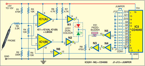
The circuit (shown in Fig. 1) is built around op-amp LM339 (IC1) and CMOS chips CD4069 (IC2) and CD4040 (IC3). CD4040 is a 12-stage ripple-carry binary counter/divider and oscillator. The tone is generated with the help of a piezobuzzer together with the divider counter. The piezobuzzer is driven by gates N3 and N5 of IC2, which are wired in anti-phase to each other. The probe can handle both TTL- and CMOS-level supply.

The logic probe comprises the op-amp (IC1) and gates N1 and N2 of IC2, which drive the dual-colour LED (LED1). Three 10-kilo-ohm resistors (R3, R4 and R5) in series provide the biasing for the two op-amps in IC1. High logic is set at two-third of the supply voltage, whereas low logic is set at one-third of the supply voltage.
When the voltage at the probe goes below one-third of the supply voltage, the output of upper op-amp/comparator IC1(A) goes low. When the probe voltage goes above two-third of the supply voltage, the output of lower comparator IC1(B) goes low, thus lighting the respective LEDs. When the red LED glows, the logic is low or ‘0’. When the green LED glows, the logic is high or ‘1’.
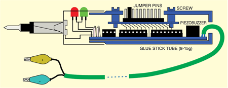
When the probe is placed at a particular frequency junction, the received clock is divided by CD4040 (IC3) to give an audio tone through the buzzer indicating the presence of frequency. The division of the signal can be selected by shifting the connector on jumper pins in the upper slot of the tube (refer Fig. 2). There are 13 jumpers to make the division between 20 (1) and 212 (4096). The use of piezobuzzer makes the probe power-efficient.
Note that the purpose of the buzzer is not to indicate the logic condition. It helps you to listen to the change in frequency at a particular pin. For instance, if you have made a 555 oscillator, using the audible probe you will be able to know whether the oscillator is working. You will also get an idea of its frequency.
In other words, the audible probe helps you to listen to changing digital signals by reducing the frequency (through a counter) to the human audible range.
Assemble the circuit on a general-purpose PCB. The entire unit can be easily accommodated within an empty glue-stick tube as shown in Fig. 2.
