


Here’s a circuit for an automatic water pump controller that manages the operation of a water pump motor. The motor automatically turns on when the water level in the overhead tank (OHT) drops below a set threshold and switches off once the tank is full.
This simple, compact, and cost-effective design uses a Single NAND gate IC (CD4011) and operates on a 12V DC power supply, with minimal power consumption.
The circuit can be divided into two main sections:

- Controller Circuit
- Indicator Circuit
Automatic Water Pump Controller Circuit
Let’s take two reference probes ‘A’ and ‘B’, placed inside the tank. Probe ‘A’ represents the lower water level, while probe ‘B’ represents the upper water level. A 12V DC power supply is connected to probe C, which defines the minimum water level that should always be maintained in the tank.
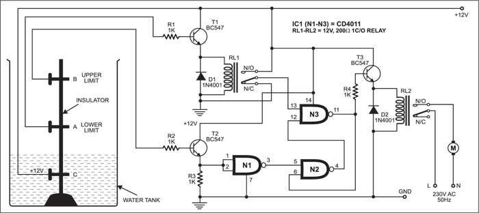
The lower-level probe ‘A’ is connected to the base of transistor T1 (BC547), with its collector linked to 12V power supply and its emitter is connected to relay RL1. Relay RL1 is also connected to pin 13 of NAND gate N3.
Similarly, the upper-level probe ‘B’ is connected to the base of transistor T2 (BC547). The collector of T2 is connected to 12V power supply, while its emitter is connected to both pins 1 and 2 of NAND gate N1 and ground via resistor R3.
The output pin 4 of NAND gate N2 is connected to pin 12 of NAND gate N3.
The output of N3 is connected to input pin 6 of N2 and the base of transistor T3 via resistor R4.
Relay RL2 connected to the emitter of transistor T3 is used to drive the motor.
Circuit Operation
If the tank is filled below probe A, transistors T1 and T2 do not conduct and the output of N3 goes high. This high output energizes relay RL2 to drive the motor, and it starts pumping water into the tank.
When the tank is filled above probe A but below probe B, water inside the tank provides base voltage to drive transistor T1 and relay RL1 energizes to make pin 13 of gate N3 high.
However, water inside the tank does not provide base voltage to transistor T2, so it does not conduct, and the logic built around NAND gates N1 and N2 outputs low to pin 12 of gate N3. The net effect is that the output of N3 remains high, and the motor continues pumping water into the tank.
When the tank is filled up to probe B level, water inside the tank still provides base voltage to transistor T1 and relay RL1 energizes to make pin 13 of gate N3 high.
At the same time, water inside the tank also provides base voltage to drive transistor T2 and the logic built around NAND gates N1 and N2 outputs high to pin 12 of gate N3. The net effect is that the output at pin 11 of N3 goes low and the motor stops pumping water into the tank.
When the water level falls below probe B but above probe A, water inside the tank still provides base voltage to transistor T1 and relay RL1 remains energized to make pin 13 of gate N3 high.
However, transistor T2 doesn’t conduct, and the logic built around NAND gates N1 and N2 outputs high to pin 12 of N3. As a result, the output of N3 remains low and the motor remains stopped.
When the water level falls below probe A, both transistors T1 and T2 do not conduct. NAND gate N3 gives a high output to drive relay RL2 and the motor restarts pumping water into the tank.
Automatic Water Pump Indicator Circuit
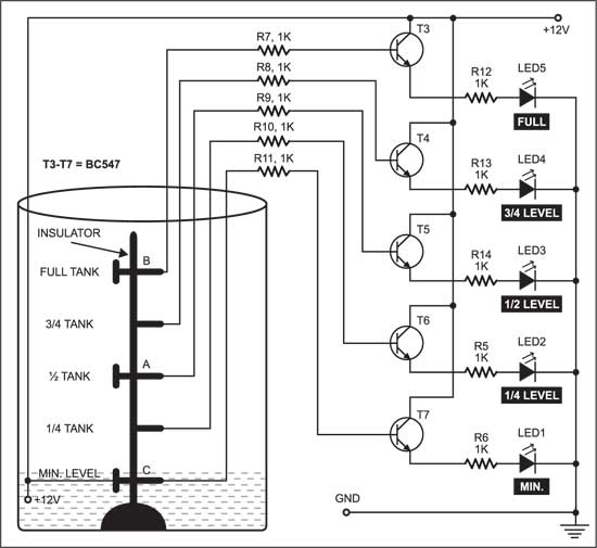
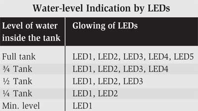
Fig. 2 shows the indicator/monitoring circuit. It consists of five LEDs, which glow to indicate the level of water in the overhead tank. Since a 12V power supply is given to water at the base of the tank, transistors T3 through T7 get base voltage and conduct to light up the LEDs (LED5 down through LED1).
When the water in the tank reaches the minimum at level C, transistor T7 conducts and LED1 glows.
When the water level rises to one-fourth of the tank, transistor T6 conducts and LED1 and LED2 glow.
When the water level rises to half of the tank, transistor T5 conducts and LED1, LED2, and LED3 glow.
When the water level rises to three-fourths of the tank, transistor T4 conducts LED1 through LED4 glow.
When the tank is full, transistor T3 conducts and all five LEDs glow. So, from the glowing LEDs, one can know the water level in the tank (see the table). The LEDs can be mounted anywhere for easy monitoring.
Note:
The user can adjust the level to which water must be filled in the tank by adjusting the heights of probes A and B. The stand and adjusting screws should be insulated to avoid shorting.
Safety Considerations
- Electrical Isolation: Ensure all electrical components, particularly the probes and relays, are properly insulated to prevent water from contacting the wiring. Utilize waterproof coatings for the probes to enhance durability.
- Proper Grounding: Always check that the system is properly grounded to avoid electrical risks and maintain user safety.
- Power source Safety: When using a 12V DC power source or higher, double-check all connections to prevent short circuits. Consider installing a fuse to provide additional protection against electrical problems
- Avoid Water-Electrical Contact: To protect the circuit from water exposure, use a sealed, waterproof housing for all control components.
Related Water Level Controller Projects
- Simple Overflow Stopper For Water Tanks
- Stop Tank Overflow With Wireless Water Level Indicator and Controller
- Water Level Indicator Circuit (LED based)
- Water Level Indicator using 7-Segment Display
- Water Tank Overflow Indicator
- Wireless Water Level Monitoring and Pump Control System
- Smart Water Meter To Help Control Water Wastage
- Water Level Detection and Alert System Using Arduino
- Ultrasonic Liquid Level Monitoring System Using MATLAB
Still looking for projects? Check Top 50 Electronics For You’s Mini Projects.
This article was first published on 3 October 2004 and was updated in January 2026.

how many tank i will use by one cotroller
Component values are not clearly discussed. Why 3 ICs will be used whereas most of the pins are useless
All the components values are provided. the circuit uses only one IC and not three
Where is resistance amps? Moreover without gnd connection how the ic will be active indivisually?
What is resistance amps?GND – take a look at 7-th pin of IC .
I need to do the opposite for my well point – i.e. when water drops to lower level Probe A the pump needs to stop – when the water rises to probe B the pump will switch on. This is to prevent the pump from loosing prime as it depletes water in the well. The water rises in the well at varying rates depending upon the season. How are the probers made?
somebody try this circuit is this working? because i want to build this circuit thanks in adance
Hi, this circuit is fully tested and working. You can make one.
This is a DC based system. I have assembled the unit published in Electronic Projects vol.7 and functions well. However it won’t give stable output in long run due to corrosion of probes, even if steel probes are used. The probes are to be changed frequently to overcome this issue.
tear down some AA size batteries and take the carbon rod as probes
It can work in 30000 thousand litre tank in my factory it can work or not
I can help you out please call me on 9674260956
I am a reader of EFY magazine for the last 20 years. Though I have not built this circuit, I have built the other one published in EFY based on 555 timer. I would like to request you to publish one such water pump controller circuit based on arduino uno without ultrasonic sensor and having pump dry run protection for lifting water from borewell.
I need a control circuit to control a submersible pump single phase which has separate START & STOP switches which are connected for a few seconds to operate. Can you help?
Hi EFY. Please i went through your Facebook page and couldn’t find the publishers of this article R Aravind and Pradeep Kumar. Please how can i reach them?
I was looking your location, address, I need this controls at Mumbai India, can you tell me who is your representative at Mumbai Malad West,
Request you kindly call back me tomorrow morning
I can help you out please call me on 9674260956
Please contact our Associates Kits’N’Spares on [email protected] or visit their website at : http://www.kitsnspares.com
Can an automatic controller be used to automatically switch on/off a 1hp pump when the public water supply (on alternate days) is available. ie: will it switch on the pump when it senses water in the public supply pipe and switch it off when the supply stops.
You may try adding another circuit given on this site: https://www.electronicsforu.com/electronics-projects/automatic-water-pump-controller
I built the circuit and works very well. But when I was testing it with a bucket full of water, the water shocked me. However I was using a 12v 2 amp smps power supply. Was that the cause? I didn’t connect the mains to the relay.
nice post and very helpful with full explanation.
Thank You for your feedback.
Hello
Thanks for the article. It will be very useful for my project.
I was just in doubt about the need for the RL1 relay.
If I connect the transistor emitter T1 to pin 13 of the NAND gate N3, wouldn’t that be enough?
Thanks
THANKS FOR NICELY DESIGNED CIRCUIT…..
BEST REGARDS
Thank you for your valuable feedback.
Thanks for sharing your knowledge. You would be kind enough to add a circuit to protect the pump in the event that the cistern does not have water. Much has been said in forums as well as on YouTube. They repeatedly focus only on this part of the circuit, leaving the complementary part (protection of the pump) unexplained. It would also be a good contribution to knowledge.
What is the use of ground symbol used in the circuit? And +12V is written along with it. Which wire is to be connected to it ?
Ground symbol is used to indicate the power supply ground (GND) or analogue ground connection. If you are using 12V battery, you need to connect negative terminal to the ground rail or on the ground symbol. 12V battery positive terminal is to be connected to any point (only point) indicated by +12V.