This ball speed checker circuit measures the speed of a cricket ball based on the time taken by the ball to travel the distance from the bowling crease to the batting crease.
Ball speed checker circuit
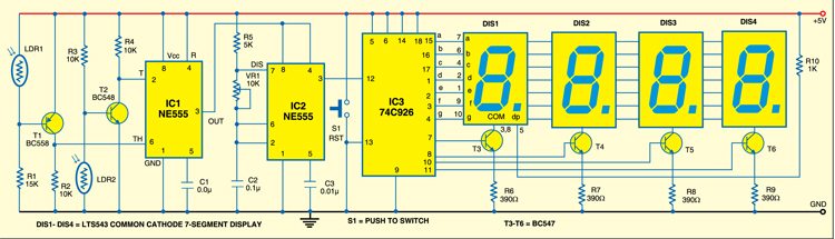
As shown in Fig. 1, the circuit is built around two NE555 timer ICs (IC1 and IC2), 74C926 (IC3), LTS543 (display) and a few discrete components.
The first NE555 timer (IC1) is wired in bistable mode. The output of IC1 is fed to pins 4 and 8 of the second NE555 timer (IC2), which is wired as an astable multivibrator and produces a frequency of 1 kHz. The output of IC2 is counted and displayed by IC3. There are two light barriers built around LDR1 and LDR2, which produce signals when the ball interrupts the laser beam falling on LDRs while passing from the bowling crease to the batting crease.
Circuit operation
When the ball crosses the bowling crease, it momentarily interrupts the IR beam falling on LDR2. This produces a pulse at pin 2 of IC1, which, in turn, sets IC1. The output of IC1 goes high and provides +5V to enable IC2 and it starts oscillating. These pulses are counted by IC3 and shown on 7-segment displays (DIS1 through DIS4).
When the ball crosses the batting crease, it again interrupts the laser beam falling on LDR1.This produces a pulse at pin 6 of IC1 and resets it. The output of IC1 goes low and stops +5V to IC2 to disable it. IC2 stops oscillating, and IC3 also stops counting.
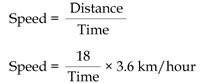
Time is displayed on 7-segment displays. The counter counts from 0 to 9999, i.e., 10 seconds. The distance from the bowling to batting crease is approximately 18 metres. You can now calculate the speed of the bowling ball by substituting the value of distance and time taken by the ball from bowling to batting crease in the following relationship:
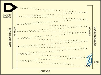
The sensor can be made by pasting two reflective mirrors on wooden bases. The mirrors must be placed face to face on the sides of the bowling crease as shown in Fig. 2. Fix a laser torch on top of one mirror. The laser beam must make a small angle after falling on the mirror placed in front of it so that the beam reflects back and forth between the mirrors until it reaches the LDR placed at the bottom of the mirror. This way the laser beam forms a light barrier. When the ball interrupts the beam, it produces a pulse. Place another such sensor at the batting side.
Construction & testing
Assemble the circuit on a general purpose PCB and enclose in a small cabinet. Wire the clock buzzer to the circuit and keep this alarm watch at a convenient place. In place of a 6V battery, you can use a 6V adaptor for powering the circuit. Mount each of the LEDs and the push button on the front panel, and connect them up to the board.
The article was first published in July 2010 and has recently been updated.