


 Normally, in mobile phones, the battery level is shown in dot or bar form. This lets you easily recognise the battery level. Here we present a battery level indicator circuit that lets you know the battery level of a device from the number of LEDs that are glowing. It uses ten LEDs in all. So if three LEDs glow, it indicates battery capacity of 30 per cent.
Unlike in mobile phones where the battery level indicator function is integrated with other functions, here only one comparator IC (LM3914) does it all. The LM3914 uses ten comparators, which are internally assembled in the voltage divider network based on the current-division rule. So it divides the battery level into ten parts.
Battery level indicator circuit
The circuit derives the power supply for its operation from the battery of the device itself. It uses ten LEDs wired in a 10-dot mode. The use of different coloured LEDs makes it easier to recognise the voltage level on the basis of the calibration made. Red LEDs (LED1 through LED3) indicate battery capacity of less than 40 per cent.
Orange LEDs (LED4 through LED6) indicate battery capacity of 40 to less than 70 per cent and green LEDs (LED7 through LED10) indicate battery capacity of 70 to under 100 per cent. The brightness of the LEDs can be adjusted by varying the value of preset VR2 between pins 6 and 7.
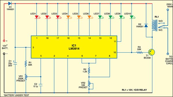
Diode D1 prevents the circuit from reverse-polarity battery connection. The tenth LED glows only when the battery capacity is full, i.e., the battery is fully charged. When the battery is fully charged, relay-driver transistor T1 conducts to energise relay RL1. This stops the battery charging through normally-open (N/O) contacts of relay RL1.
For calibration, connect 15V variable, regulated power supply and initially set it at 3V. Slowly adjust VR1 until LED1 glows. Now, increase the input voltage to 15V in steps of 1.
2V until the corresponding LED (LED2 through LED10) lights up.
Now the circuit is ready to show any battery voltage value with respect to the maximum voltage. As the number of LEDs is ten, we can easily consider one LED for 10 per cent of the maximum voltage.
Construction
Connect the voltage from any battery to be tested at the input probes of the circuit. By examining the number of LEDs glowing you can easily know the status of the battery. Suppose five LEDs are glowing. In this case, the battery capacity is 50 to 59 per cent of its maximum value.
Assemble the circuit on a general-purpose PCB. Calibrate it and then enclose in a box.
Feel interested? check out other electronics projects.

Can we find out the battery percentage in the monitor..?
You can label the percentage near the LEDs as explained in the article but cannot show on the monitor