


Do you want to get an early warning of brake failure while driving? Here is a brake failure indicator circuit that constantly monitors the condition of the brake and gives an audio-visual indication. When the brake is applied, the green LED blinks and the piezobuzzer beeps for around one second if the brake system is intact. If the brake fails, the red LED glows and the buzzer stops beeping.
The circuit will work only in vehicles with negative grounding. It also gives an indication of brake switch failure.
In hydraulic brake systems of vehicles, a brake switch is mounted on the brake cylinder to operate the rear brake lamps. The brake switch is fluid-operated and doesn’t function if the fluid pressure drops due to leakage. The fluid leakage cannot be detected easily unless there is a severe pressure drop in the brake pedal. This circuit senses the chance of a brake failure by monitoring the brake switch and reminds you of the condition of the brake every time the brake is applied.

Brake failure indicator circuit
The circuit uses an op-amp IC CA3140 (IC2) as voltage comparator and timer NE555 (IC3) in monostable configuration for alarm. Voltage comparator IC2 senses the voltage level across the brake switch. Its non-inverting input (pin 3) gets half the supply voltage through potential divider resistors R3 and R4 of 10 kilo-ohms each. The inverting input (pin 2) of IC2 is connected to the brake switch through diode D1, IC 7812 (IC1) and resistor R2. It receives a higher voltage when the brake is applied.
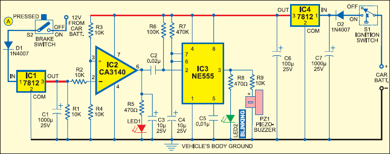
Normally, when the brake is not applied, the output of IC2 remains high and the red LED (LED1) glows. The output of IC2 is fed to trigger pin 2 of the monostable through coupling capacitor C2. Resistor R1 is used for the input stability of IC2. IC1 and C1 provide a ripple-free regulated supply to the inverting input of IC2.

IC3 is wired as a monostable to give pulse output of one second. Timing elements R7 and C4 make the output high for one second to activate the buzzer and LED2. Usually, the trigger pin of IC3 is high due to R6 and the buzzer and LED2 remain ‘off.’
When the brake pedal is pressed, pin 2 of IC2 gets a higher voltage from the brake switch and its output goes low to switch off the red LED. The low output of IC2 gives a short negative pulse to the monostable through C2 to trigger it. This activates the buzzer and LED2 to indicate that the brake system is working. When there is pressure drop in the brake system due to leakage, LED1 remains ‘on’ and the buzzer does not sound when the brake is applied.
Construction & testing
The circuit can be assembled on any general-purpose PCB or perforated board. Connect point A to that terminal of the brake switch which goes to the brake lamps. The circuit can be powered from the vehicle’s battery.
The circuit requires well-regulated power supply to avoid unwanted triggering while the battery is charging from the dynamo. IC4, C6 and C7 provide regulated 12V to the circuit. The power supply should be taken from the ignition switch and the circuit ground should be clamped to the vehicle’s body. A bicolour LED can be used in place of LED1 and LED2 if desired.


excellent
Circuit diagram aur components to bateaye
It’s already in the circuit diagram
can we use normal 12 v battery instead of car battery in this project???
Don’t you have the video?
can you help me please i wanna do this project
Kindly elaborate your query.
This circuit are not working.
No.compulsary working of this circuit
is it possible to use digital pressure to sense the pressure instead of using brake pedal, in order to increase the efficiency and accurate pressure decrease
if brake is not applied then red LED will glow?
Plz reply asap
BREAK WIRE CONNECTING LOCATION PLS EXPLAIN.
Any video links of the assembly of components
i want a vedio please
How do we indicate the pressure leakage and brake failure in this circuit??