


 High-quality audio amplifiers require a very efficient power supply with negligible ripple, hum and buzz. An ordinary bridge-type power supply has a drawback in that it drops to 3 to 4 volts when connected to the load. A transistor- or IC-regulated power supply is much better option but still it has some ripple and hum objectionable to sharp ears.
Here is the circuit of a highly efficient power supply with regulation that uses a centre-tapped transformer.
The 15V AC secondary output drops by 0.6Vx4=2.4 volts after passing through the rectifier bridge. Further, the resistance of the transformer coil drops to 0.5V and the ripple accounts for 1V. So the total drop is about 4V DC. This is why the transformer’s secondary output should be at least four volts higher than the regulated output.

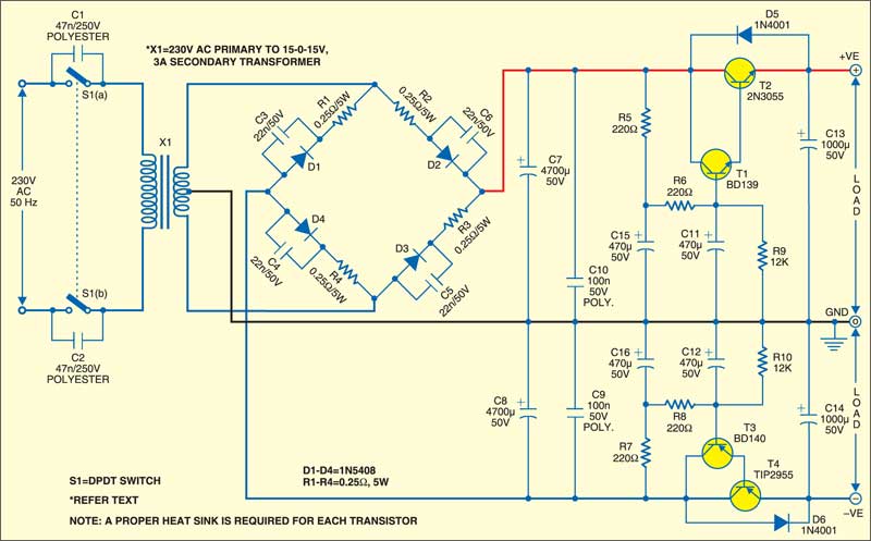
As shown in the circuit, two Darlington pairs of transistors (T1-T2 and T3-T4) are used as regulators. The Darlington pairs of transistors increase the current gain. The 470µF capacitors connected to the base of transistors T1 and T3 reduce hum and also depress higher-order harmonics. The 12-kilo-ohm resistors (R9 and R10) compensate for variations in the transistor gain. Resistors R1 through R4 (0.25-ohm, 5W) are used in series with diodes to limit the peak current at power-on.
Capacitors C3 through C6 (22nF, 50V) reduce the internal thermal noise of respective diodes. Mains filter capacitors C7 and C8 (4700µF) are shunted by capacitors C9 and C10 (100nF, 50V), respectively, to reduce the RF noise. Capacitors C1 and C2 (47nF, 250V) used across double-pole, double-throw switch S1 eliminate bounce.
Resistors R5 through R8 (220-ohm) and R9 and R10 (12-kilo-ohm) are 0.25W metal-film or 0.5W carbon resistors. If 10,000µF capacitors are used in place of 4700µF C7 and C8, any variations in mains (200V-260V AC) will not affect the DC output.
Ground all the electrolytic capacitors at a common point. Use a copper bar or a small copper plate as the common ground. Transistors T1 through T4 must be used along with heat-sinks. Connect other components of the circuit to the common ground using copper wire of a minimum 16 SWG.
EFY note. When testing at the EFY lab, a 230V AC primary to 15V-0-15V, 3A secondary transformer was used to get ±15V DC, 2A. Choose the voltage and current ratings of the transformer’s secondary coil anywhere between 18V and 22V as per your requirement without changing any component.