


Protect your costly vehicle from theft using this electronic car porch guard system. The system immediately switches on the porch lamp and sounds a loud alarm as soon as it detects any attempt of impending theft.
A shrewd thief will not attempt to start the vehicle immediately but disarm the safety alarm installed in the vehicle before taking the vehicle out of the garage at night. So it would be very difficult to detect the theft and the loss would be realized only next morning. This circuit triggers an alarm when the car is moved out of the parked area so as to thwart any attempt by the burglar.
Car Porch Guard Circuit

Fig. 1 shows the circuit of the car porch guard. It is basically a vibration detector alarm that makes use of a piezo element as the sensor. The piezo element typically has a capacitance of a few tens of nanofarads and will be readily charged if a potential is applied across its terminals. The piezo element gets charged through resistors R1 and R2 and retains this charge until it is subjected to mechanical vibrations.

Recommended: Interesting Electronics Projects
When the piezo element senses any vibrations, it generates an AC voltage across its terminals, which is amplified by transistors T1 and T2. When T2 conducts, capacitor C1 gets charged and a voltage is applied to the inverting input (pin 3) of IC LM311 (IC1).

IC LM311 is a voltage comparator whose pin connections are different from those of other standard op-amps. Its output stage has both positive (pin 7) and negative (pin 1) outputs to enhance flexibility. The negative output is usually grounded. The output has an npn transistor with pin 7 forming its collector and pin 1 forming its emitter. So the IC will sink current when the output transistor conducts.
Circuit operation
When IC1 is triggered using the emitter voltage of T2, its output sinks through R4 and LED1 glows. The reference voltage for IC1 is provided by divider preset VR1. The high-to-low going transition at the output of IC1 is used to trigger the monostable (IC2). Based on the values of R7 and C5, the output of IC2 remains high for about three minutes. Resistor R6 and capacitor C3 are time-delay components for the reset pin of IC2 to avoid false triggering.
The output of IC2 is used to trigger triac BT136 and activate alarm tone generator IC3. The triac completes the circuit of the lamp through its MT2 and MT1 terminals. IC3 has an internal oscillator whose oscillation frequency is fixed by resistor R10. Pin 6 of IC3 is shorted to Vcc pin 5 to get a police siren. The output of IC3 is amplified by transistor T3.
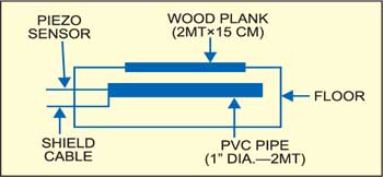
The piezosensor is a low-cost, readily available buzzer without oscillator. Mount it on one end of a 2m long PVC pipe. Close the other end using a cap so that the pipe acts as a resonator to increase the sensitivity of the piezosensor. Connect the piezosensor to the circuit using a single-core, shielded wire, which should be properly concealed.
Construction & testing
Assemble the circuit on a general-purpose PCB and enclose it, except the piezo sensor, in a suitable cabinet.
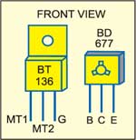
Fix the PVC pipe with the sensor to a wooden plank (2m long and 15cm wide) using nuts and bolts. The wooden plank should be fixed across the car porch entrance so as to keep the PVC pipe below the floor surface as shown in Fig. 2. As the car is moved over the wooden plank, the vibrations created by its motion will be sensed by the piezosensor to activate the alarm. Fig. 3 shows pin configurations of triac BT136 and transistor BD677.
The article was first published in April 2006 and has recently been updated.
