


 The overflow alert system presented here will electronically monitor cistern (tank that holds water to flush the toilet) overflows that can otherwise cause seepage in the flats below in a multi-storied building. In case the cistern’s mechanism falters and water starts overflowing, it will sound an alarm to alert you with noticeable audible and visual warnings.
The sensor of the system comprises stainless-steel electrodes (needles) housed in a 2.54cm (1-inch) diameter connector (with a small outlet tube attached) for fitting directly into the side overflow pipe of a concealed flushing cistern that also has an internal overflow arrangement. It can be inserted easily into the overflow hole, and detection level can be set as per requirement. Signals from the sensor can be channelled to the master (alarm) unit with a low-voltage twin cable.
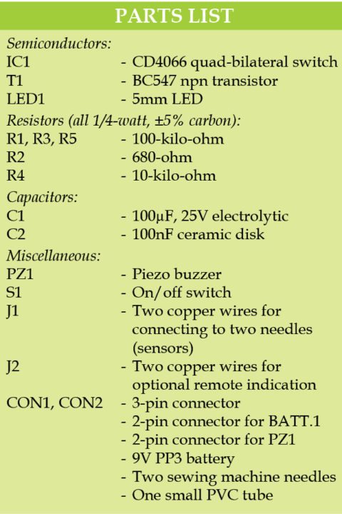

The master unit is housed in a wall-mounted plastic enclosure. Power supply is provided from a standard 9V battery. Besides, a volt-free switch terminal is provided for optional remote overflow indication to the building’s caretaker for a central common alarm.
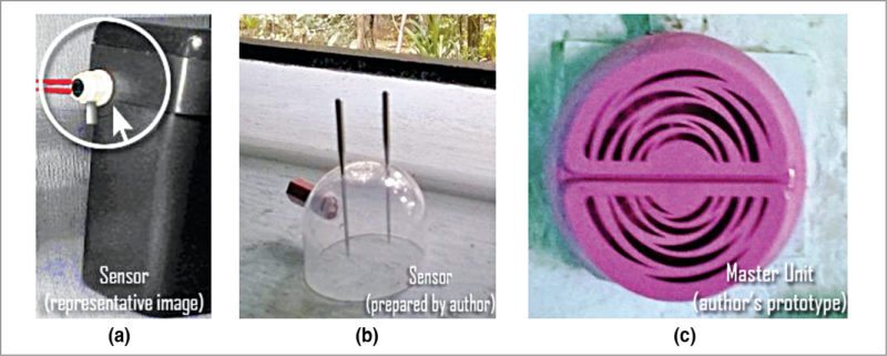
Fig. 1(a) shows the sensor of the cistern overflow alert system, Fig. 1(b) the sensor made by the author with the help of a 2.54cm diameter bottle cap, two sewing machine needles and one small PVC tube, and Fig 1(c) the shell of a discarded restroom air-freshener used as prototype enclosure, wall-mounted in the author’s toilet.
Circuit and working
Circuit diagram of the master unit of the cistern overflow alert system is shown in Fig. 2.
The master unit is built around quad-bilateral switch CD4066 (IC1), in which switches IC1A and IC1B simultaneously extend positive supply to the output. These are driven by the water sensor (connected to J1) through IC1A.

Overflow alert visual indicator (LED1) is driven by IC1A, and the aural indicator (PZ1) is switched on by IC1B with the help of BC547 transistor (T1). IC1C (connected to J2) works as a volt-free normally-open (N/O) bilateral switch for optional remote overflow indication. Maximum current through this switch should be less than 20mA.
As shown in the circuit, three (of the four) electronic switches in CD4066 control device operation. In the case of an overflow, IC1A is closed due to the high level at its control input (pin 13); LED1 lights up to indicate its status. At the same time, IC1B is closed too, causing PZ1 to be active.
In idle state, voltage at the control inputs of all switches in IC1 drops to zero, causing the switches to open. Overflow detection threshold may be adjusted by using appropriate value of resistor R1. Switch S1, when opened, prevents the battery from being discharged when the device is not in use for some reason.
Further, output from the active piezo buzzer should be loud enough to alert you. If desired, a more powerful piezo sounder can be used instead.
Construction and testing
An actual-size, single-side PCB layout of the cistern overflow alert system is shown in Fig. 3 and its component layout in Fig. 4. Assemble the circuit on the PCB.

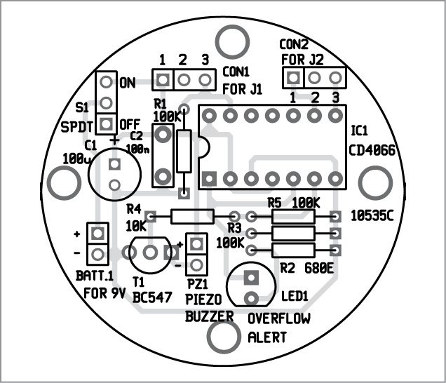
Download PCB and component layout PDFs: click here
Use a 9V PP3 battery or suitable DC power supply. Connect the cistern sensors to the PCB at CON1 using two wires (J1). Connect two copper wires at CON2 for extension to optional remote indication (detail not shown here). Place the assembled unit at a suitable location for monitoring water overflow condition.
T.K. Hareendran is founder and promoter of TechNode Protolabz
