


 Thwart the attempt of burglary by detecting intrusion with this alarm circuit. Each door is protected by a separate circuit built around an independent 555 timer IC in conjunction with reed switch magnet. All the three units are powered from a single power source. The buzzer can be plugged into the earth line of a socket in any room of the same building having proper earth line connection. There is no need of laying external wires up to the buzzer unit from different rooms.
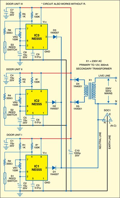
For door-1 alarm unit, connect reed switch S1 near the magnet of gate 1. Wire IC1 as a frequency oscillator and set door-1 alarm unit to the desired frequency, say, between 1 Hz and 3 Hz, using VR1. For door-2 alarm unit, connect reed switch S2 near the magnet of gate 2. Wire IC2 also as a frequency oscillator and set door-2 alarm frequency between 5 and 7 Hz using VR2. For door-3 alarm unit, connect reed switch S3 near the magnet of gate 3. Wire IC3 also as a frequency oscillator and set door-3 alarm frequency between 10 and 12 Hz using VR3.
The power supply required to operate the alarm circuits consists of a bridge rectifier and filter capacitor C10. In normal condition, i.e., when all the doors are closed, reset pin 4 of IC1 through IC3 remains low. As a result, these do not oscillate and piezobuzzer PZ1 remains silent.

When door 1 is opened, the magnet moves away from reed switch S1. IC1 generates 1-3Hz signals and the piezobuzzer beeps to indicate that door 1 has been opened. When door 2 is opened, IC2 generates 5-7Hz signals and the piezobuzzer beeps to indicate that door 2 has been opened. Similarly, when door 3 is opened, the piezobuzzer beeps at the rate of 10 to 12 Hz, indicating that door 3 has been opened.
Thus sitting in a room where the buzzer unit is fitted, you can easily know (through the typical sound of the buzzer) which room has someone gained entry into.
Assemble the circuit on a general-purpose PCB and connect the output to any socket (SOC1) inside the building as shown in Fig. 1. Mains line wire is not connected to SOC1. Live and neutral wires are connected to the primary of the step-down transformer, which is a part of the power supply. All the three units connected are powered from a single rectified power supply. Connect the reed switch near the particular gate magnet through an external wire.
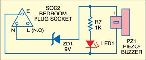
Plug-in the piezobuzzer into the earth and neutral lines of socket (SOC2) fitted in the desired room of the same building. There is no need of laying external wires up to the buzzer unit. This project will work off the power line within the building.
EFY lab. In the buzzer unit, a zener diode (ZD1) is used as the voltage between earth and neutral is around 9V instead of 0V. If you find the ideal voltage difference of zero volt between earth and neutral lines, the circuit will work even without ZD1 in the circuit.