Continued from Customised Solution for Measurements: Building a Personal Multimeter (Part-1)
Once we are done measuring the voltage and current, let’s take a look at the other measurable parameters that can be handled by a Digital Multimeter.
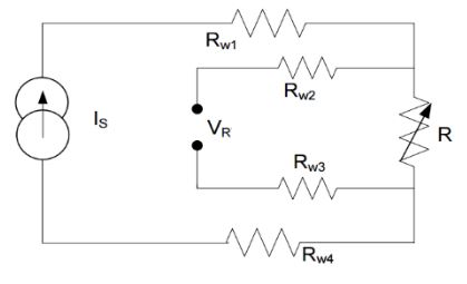
Resistance Measurement: There are several methods to measure resistance. The four wire measurement is the most useful as it greatly reduces the error due to wire resistances. In this method, a known constant current is passed through the unknown resistor R. The voltage across it is measured using a separate sensing path.

The separate sensing path ensures that the voltage drop across the wire resistances, Rw1 and Rw4, does not affect the voltage measured. There is little voltage drop across resistances Rw2 and Rw3, which are in the ADC measurement path, because there is negligible current flow into the high-input impedance terminals of the ADC. The unknown resistor in this method is given by the equation R=V/I.
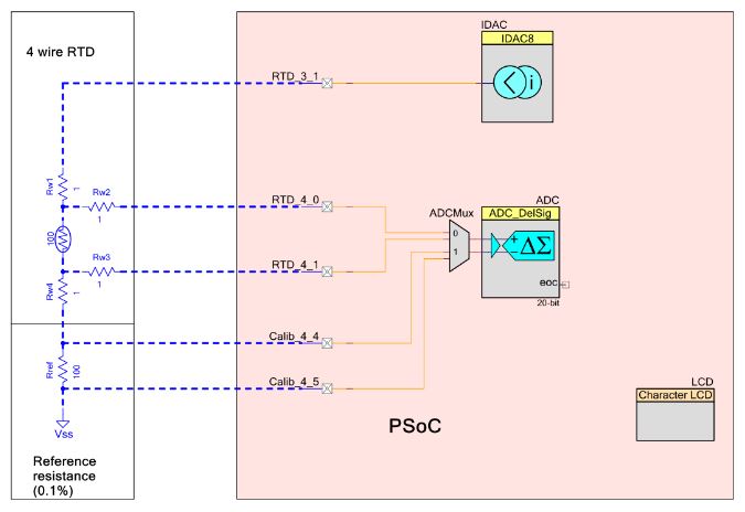
To find the unknown resistance, the current source and the ADC measuring the voltage must be accurate. Specifically, the current source and the ADC should be free from offset, gain and non-linearity errors. Even a small error in voltage measurement can result in a large temperature error at higher temperatures. To overcome the gain/offset error caused by the ADC and the current DAC (IDAC), a reference resistor can be added to the design.

Capacitance measurement: DMM uses multiple methods for capacitance measurement. Some of them have been mentioned below.
RC Oscillator Method: In this method, the capacitance to be measured is made part of an RC oscillator and the frequency of the RC oscillator varies with change in capacitance. Figure -8 shows an RC oscillator using 555 timer and Figure-9 shows an RC oscillator using inverters.
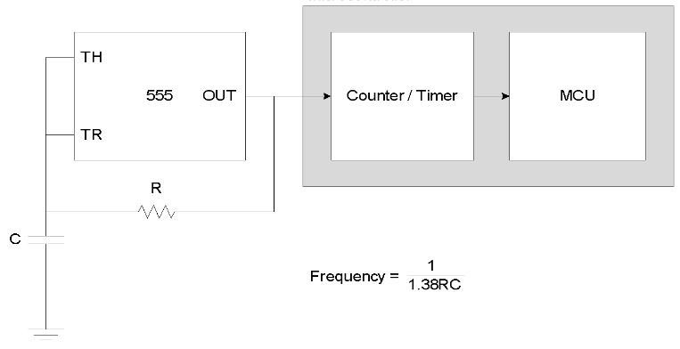
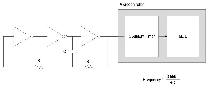
The output of the oscillator can then be fed to a counter to count the number of cycles in a second to measure the frequency and calculate the capacitance using this value.
Alternatively, the oscillator output can be connected to a timer and period can be measured using capture functionality of the timer. Capacitance can be calculated using this value. This method requires external components to construct the RC oscillator and also the oscillator frequency is sensitive to power supply variations.
Single Slope Method: In this method, a constant current source is used to charge the capacitor. The time taken to charge the capacitor to a known voltage can be used to measure capacitance.
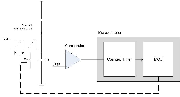
In the above circuit, the microcontroller first keeps the switch SW (could be a general purpose input/output or an external field effect transistor) closed, thus holding the capacitor in a discharged state. Then the microcontroller releases the switch. The constant current source charges the capacitor, and the voltage across the capacitor ramps up linearly. When the voltage across the capacitor crosses VREF, the comparator output goes high. The microcontroller uses the Timer/Counter to measure this time duration and then calculates C using below equation.
C=I t/V
where:
I = Current from the constant current source
V = Reference voltage of the comparator
t = Time taken to charge the capacitor to VREF
The accuracy of capacitance measurement with this method depends on the accuracy of the constant current source and reference voltage of the comparator.
Sigma Delta Modulator Method: In this method, a Sigma Delta modulator converts the capacitance into a digital bit stream where the density of the bit stream is directly proportional to the capacitance.
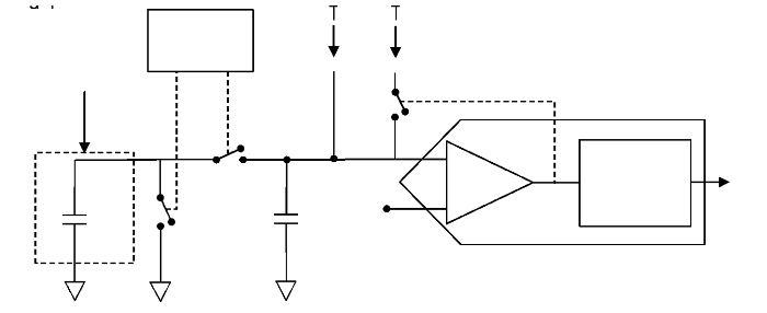
IDACMOD is a current source that charges a modulation capacitor CMOD. When the voltage across CMOD goes above VREF, output of the comparator goes low and turns off IDACMOD.
Cx is the capacitance to be measured. SW1 and SW2 along with Cx form a switch capacitor cell. SW1 and SW2 are driven out of phase by a clock source. When SW2 is turned ON, some charge is transferred from CMOD to Cx. When SW1 is turned on, Cx is discharged. Thus Cx, SW1 and SW2 together act as a resistor discharging CMOD. As CMOD is discharged, the voltage drops and when the voltage drops below the hysteresis of the comparator, output of the comparator goes high and turns on IDACMOD which starts the charging cycle. IDACCOMP is a fixed current source that can be used to increase the dynamic range of measurement.
Why go for PSoC?
PSoC supports CapSense technology, which replaces mechanical buttons with a CapSense based keypad. This reduces failure due to mechanical buttons and provides better product reliability. CapSense SmartSense component, auto-tunes the sensitivity of buttons and slide.
It can drive LED and LCD displays (Segment LCD, Graphic LCD and Character LCD displays) for displaying channel and volume information. With an operating range of 1.71V to 5.5V it can interface with external peripherals for other applications.
It has internal PGA, comparators and configurable delta-sigma ADC with 8 to 20-bit resolution with Sample rates up to 192 ksps. It is used to measure different Analog inputs and Battery inputs.
An internal RTC component for real time measurement and hence does not require external clock/oscillator circuitry.
With support for USB 2.0 interface it allows the user to interface external memory (hard disk) through USB 2.0. It supports secure digital (SD) card interface. It has an internal 8-bit DAC, which can be used for controlling speaker volume and also performs mute function for the audio speaker.
PSoC is a combination of microcontroller and ASIC. PSoC provides an ease-of-use environment, Using PSoC in DMM applications helps to reduce the product cost (by reducing BOM cost) and project cost (with PSoC creator and PSoC designer implementation). So, begin making your own DMMs.
Shared by Ronak Desai and Arijit Karmakar, Cypress Semiconductor