


 Here’s a low-cost DC to DC converter circuit that converts 6V DC into 12V DC. It uses no transformer and is easy to construct with few components.
The circuit is built around IC 555, which generates the required frequency of around 2 to 10 kHz to drive power transistor BD139 (T2). The output frequency of the IC can be adjusted by a 47k potmeter (VR1) and given to the base of transistor T2 via resistor R3. Transistor T2 is mounted on an aluminium heat-sink. Inductor L1 and capacitor C5 (2200µF, 35V) are energy storage components. The 12V zener diode regulates the voltage across the output of the circuit.
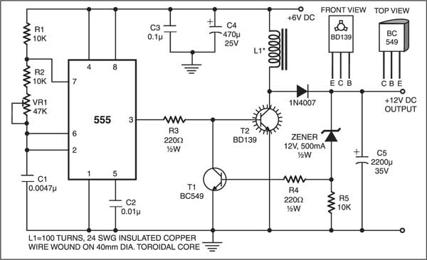
The inductor comprises 100 turns of 24SWG enameled copper wire wound on a 40mm dia. toroidal ferrite core. The more the turns on the core, the higher the current delivering capability of the circuit to the load at the output.
The output current is controlled by transistor BC549 (T1) with the help of resistors R4 and R5. The output voltage is controlled by the zener diode and smoothed by capacitor C5.
You can obtain regulated 12V DC, 120 mA across the output of this circuit. At higher loads (below 100 ohms), the circuit might not perform well and deliver as much current. Use a large capacitor (C5) and inductor for higher voltages and higher currents, respectively. Different output voltages can be obtained by using zener diodes of other ratings.