
 In analogue electronics, oscillators and their implementation using integrated circuits (ICs) is an important subject. As 555 timer IC is easy to understand and flexible enough to suit diverse applications, it is used in astable multivibrator (oscillator) configuration for study purpose. While covering the topic in the classroom, instructors often use circuit simulators such as Proteus and TINA to show the output waveform variation of 555 timer IC by changing the resistor or capacitor values.
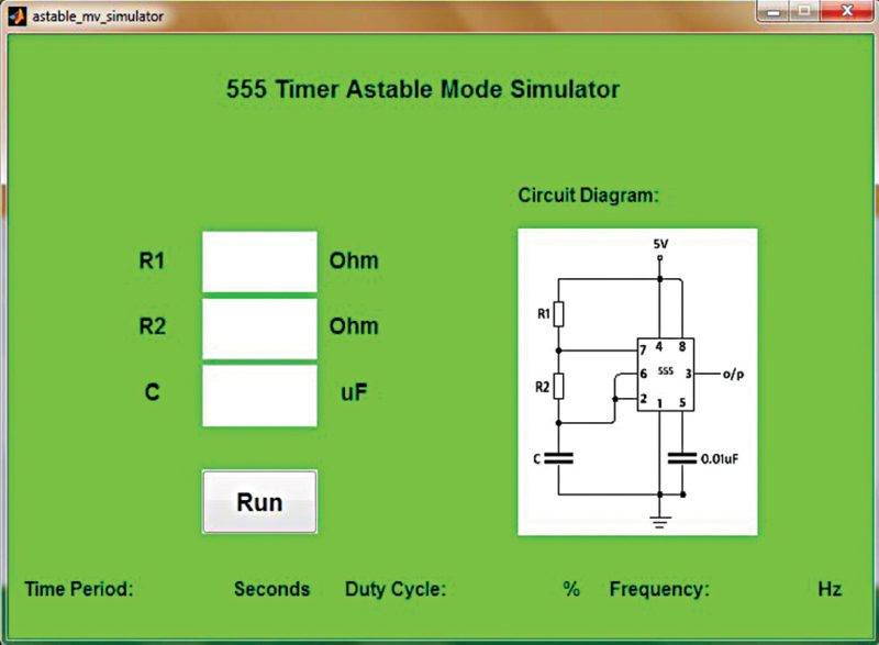
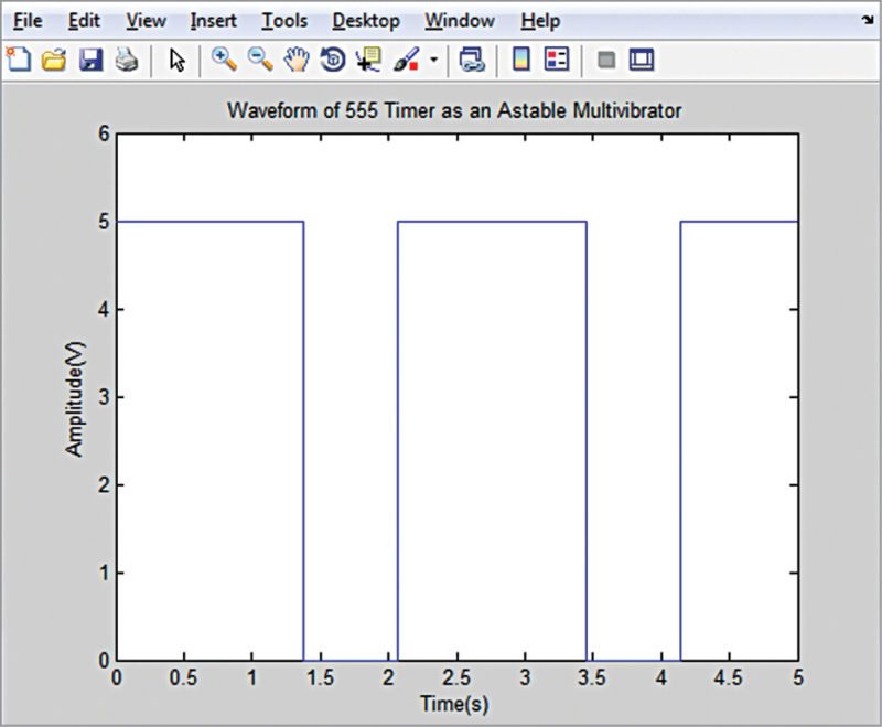
We present here a demo program for a 555 timer-based astable multivibrator, which is implemented using the graphical user interface (GUI) in MATLAB 2014 environment, as shown in Fig. 1. Two resistors and a capacitor are required to operate 555 timer IC in astable mode. When the user enters values of the external components (R1, R2 and C) and presses ‘Run’ button, the simulator provides the time period, frequency and duty cycle of the square wave. The program also shows the output square waveform in the figure window (Fig. 2). The GUI also shows the circuit diagram for operating timer 555 in astable mode.
Software
As mentioned before, 555 timer IC is used in astable mode in order to produce a square wave. Time period (or frequency) and duty cycle of the astable multivibrator is determined by external components R1, R2 and C (refer to the circuit diagram in Fig. 1).
The time during which the output is high:
Th=0.693×(R1+R2)×C seconds
The time during which the output is low:
Tl=0.693×R2×C seconds

Therefore the time period of the square wave is:
T=Th+Tl=0.693×{R1+(2×R2)}× C seconds
and frequency in Hertz (Hz) is:
f=1/T=1.44/{R1+(2×R2)}×C
The duty cycle of the square waveform=Th/(h+Tl)×100%= (Th/T)×100%

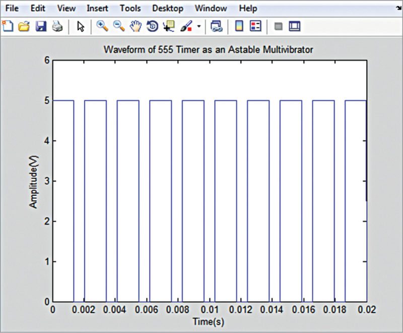
The user must enter the values of R1, R2 and C, and click ‘Run’ in order to simulate the astable mode operation of 555 timer IC. On clicking ‘Run’ button, MATLAB executes a callback function to calculate and display the time period, frequency and duty cycle, and plots the waveform. The waveforms for two different sets of component values are shown in Figs 2 and 3, respectively.
You can also try out the following by building upon this work:
1. Plot voltage variation across capacitor C
2. Change the supply voltage from 5V to 10V and plot the output waveform; you will find that the amplitude of the output varies
3. Connect a diode (anode to pin 7 of IC and cathode to pin 6) in parallel with R2 and plot the output waveform; you get a 50% duty-cycle output waveform.


