


This simple DIAC controlled flasher finds various industrial applications as a high-voltage indicator or machine-’on’ indicator. It flashes once every second to give a warning indication and is simple to design. The project can be wired lead-to-lead without using PCB. It is directly powered from 220V AC and can be enclosed in the mains box.
DIAC Controlled Flasher Circuit
Mains 230V AC is rectified by D1, which reduces it to a safer level through 33-kilo-ohm resistor R1. Capacitor C1 (470µF, 100V) charges through diode D1 and resistor R1, which reduces the flow of current to the diac and hence the triac remains non-conducting.
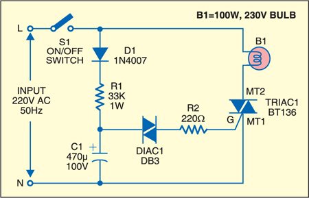
After capacitor C1 is fully charged, the voltage across the diac rises and it conducts. This provides gate current to the triac through R2. The triac fires and completes the circuit of the lamp and it glows.

The triac (BT136) comprises two silicon-controlled rectifiers (SCRs) connected in the reverse parallel configurtion, sharing the same gate circuit. When the triac fires, both the SCR portions conduct. The gate of the triac is quite complex and it can be triggered by DC, rectified AC, AC or pulse sources like neon lamps or switching diodes like diacs.
When the diac conducts, capacitor C1 discharges through the diac and R2. This reduces the gate current of the triac and it switches off. The lamp again turns on when C1 charges again. Thus the charging-discharging cycle of capacitor C1 determines the flash rate of the lamp.

Construction & testing
Since the circuit uses 220V AC, all the points are at mains lethal potential. Adequate spacing and use of lead sleeving is required as saftey measures while assembling the circuit. Do not enclose the circuit in a metallic cabinet unless it is made fully shockproof. Also, do not solder or desolder the components when the circuit is powered.
The article was first published in July 2007 and has recenlty been updated.

Very interesting circuit. I am novice at this and a bit if “tinkerer” guy. Being in north america, it will be 120 VAC instead of 220.
1) Will the values of the different components should be adjusted or the same values will do?
2) How to determine or have a fix rate of flashing ( let’s say 40hz)
Thanks for any comments or insights that could help with project
Robert